Around the
radiator.
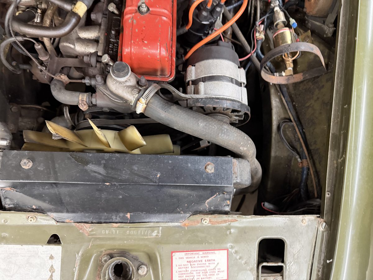
The cooling stack sits among distinct panels and supports. The current photo-guided cover and cooling-frame reconstruction replaces the old high/rearward upper envelope. The visible cover is modeled once; the hidden factory cowl/apron/guard interface remains unresolved.
The revised front nose, GAN6 mesh intake and bumper supports ↗ replace the old solid nose/chrome-grille backing. Their apertures and mounting relationships remain estimates; no radiator removal clearance or cooling performance is established.
Current landing-panel relationship
The latest cooling revision lowers and moves the rear tongue edge to the declared cowl front/top reference. Its body-coordinate endpoints are [−311, 639.2, 1133.9] and [191, 639.2, 1133.9] mm, all conditional construction stations. Front platform, nose, latch and access openings stay. The rear span is about 137.5 mm instead of the former 237.5 mm. No fitted panel seam, fastening, body survey or removal path is established. Inspect the current panel ↗
Earlier front-panel construction
The earlier dimensions and retained-cowl statements below describe the superseded rear-tongue stage; use the current relationship above for the model.
The native front landing panel now retains its original nose, latch and access-opening stations while adding a tapered rising rear tongue toward the cowl front/top edge. The old references stopped about 304 mm apart longitudinally. That was a difference between drawing edges, not a measured gap on this car.
IMG_6853/6854 support painted structure beside the cowl, but do not establish the hidden outline or folds. This extension is an uncalibrated reconstruction hypothesis. Its width, slope, 1.5 mm projected gauge and edge contact are estimates. The engine, radiator, fan, cowl and nose have not moved. Small source intersections with the independent wheelhouse references remain recorded; no actual interference is inferred.
The panel adds a body obstacle when studying radiator access. It does not establish an upper screw counterpart, a bolted or welded joint, a sealed air duct, a load path or a removal route. It stays fixed during illustrative separation. The separate guard and its upper screw comparisons remain in the cooling attachment study.
Inspect each relationship
The revised cowl overlaps the modeled fan at sampled rotation angles. The source rotation report ↗ records the finding. Neither part was moved to eliminate it. This is a reconstruction discrepancy, not proof of interference on the actual car or a fitted-clearance result.
What the evidence supports
The factory 1500 cooling plate, PDF p. 88 ↗ separates CHA281 cowl, radiator fixings, top fixings and CHA420 fan guard. The separate guard is modeled as a supplier/photo comparison in the cooling attachment study; its fitted identity remains unverified. IMG_6853/6854 show the visible apron and front painted panel.
British Motor Heritage’s body drawing ↗ supplies a handed mounting-bracket comparison. Its repair-panel catalog ↗ distinguishes the lower tray. These are architectural comparisons; they do not identify the installed panels or repair history.
What remains estimated
All sheet gauges, folds, aperture sizes, brackets, hole centers, screw cues, support contacts and common body/cooling stations are estimates. The radiator core dimensions are a replacement comparison, not an owner survey. An opening drawn around that comparison does not establish fan sweep clearance, hose relief or fixing fit.
The four body references remain fixed during general separation. No welded-panel removal, radiator lifting route, latch/catch operation, tool path or service sequence is validated. Use the model to distinguish structures and compare visible connections before consulting the complete applicable workshop procedure.