Three joints.
One casting.
The 1500’s water-pump housing joins the engine, the separate pump, and the thermostat outlet. This guide shows which joint each gasket and fastener belongs to. The current virtual casting has the right parts but does not yet have measured distances between their mounting faces.
Housing to head
Gasket 138702 has two coolant openings and three bolt holes. Three housing bolts have different catalogue lengths. The real casting decides their positions.
Pump to housing
Gasket 138701 seals the round impeller opening. Three separate studs and nuts hold the pump flange. These are not the housing-to-head bolts.
Thermostat assembly
The outlet uses a separate GTG103 gasket and two screws in the factory parts list: CHA440 at 1¼ in and CHA441 at 1 in. Their positions on this car and its 1975 outlet variant still need identification.
Lower-hose inlet and tapped ports
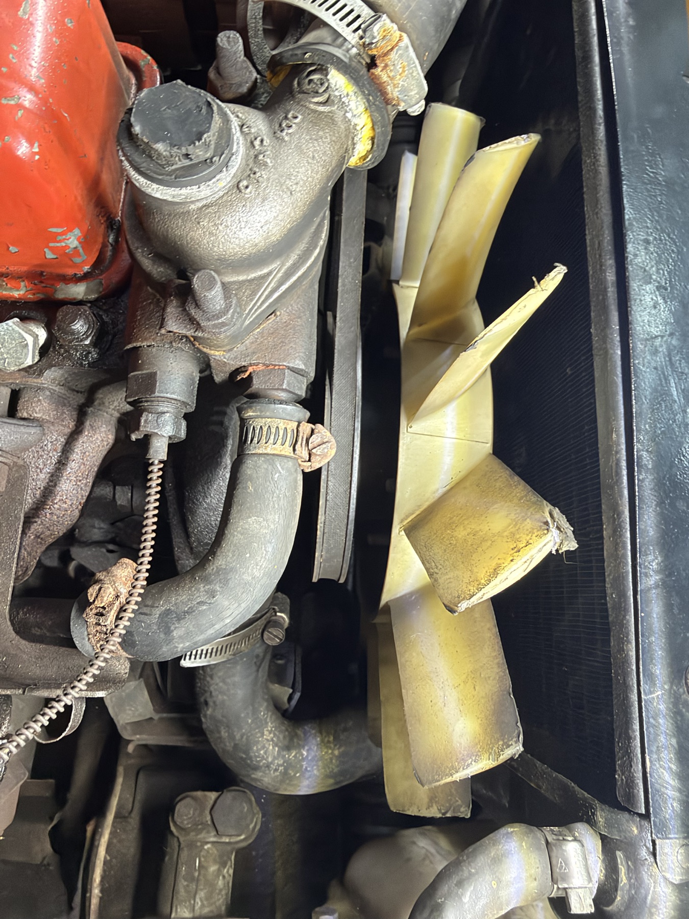
The 144297A replacement-casting photograph makes the long lower-hose neck and two tapped bosses clear. IMG_6895 shows a lower hose, clamp and wired fitting on this car, but does not expose the complete casting or the second port. The 3D housing now includes those features for identification. The neck’s roughly 34 mm outside diameter and 47 mm projection are scaled from the oblique supplier image; neither is a verified fitment measurement.
Before ordering a hose, clamp, sender or adaptor, record the casting mark and photograph the neck, both tapped ports and every attached fitting with the engine cold. Measure the metal neck outside the bead and the actual hose bore separately. Keep the upper and lower hose routes distinct; the 3D study currently shows only the housing inlet, not the full lower-hose bend or radiator connection.
The protected line in IMG_6895 appears to be a capillary temperature-gauge connection. That fits the Moss instructions for Midget 1500 gauges through 1977: they name the 11K2846 / 361-065 adaptor and AED172 / 324-805 copper washer for a capillary bulb. The 1500 cooling list assigns the later electrical sender to chassis 200001 onward (1978). The 3D model now separates the comparison adaptor, washer and short bulb/nut end. Confirm the actual gauge and line on this car before buying a sender or loosening the fitting; the model does not establish its thread or the line’s route to the dash.
The three housing bolts
The Moss Europe Midget 1500 cooling drawing, printed p. 136 numbers the bolts 14–16. Its facing list gives one of each length, all 5/16 UNF with GHF332 spring washers. The diagram below is a face-on checklist of the photo-scaled 138702 gasket, not a view of this casting installed in the car. The drawing’s oblique left/right assignment needs checking against the real housing.
| Moss item | Catalogue part | Nominal bolt length | What to verify on the car |
|---|---|---|---|
| 14 · upper | BH605221 | 5/16 UNF × 2¾ in (69.85 mm) | Which upper hole, washer and actual under-head length |
| 15 · drawing left | BH605191 | 5/16 UNF × 2⅜ in (60.33 mm) | Installed side, washer and actual under-head length |
| 16 · drawing right | BH605181 | 5/16 UNF × 2¼ in (57.15 mm) | Installed side, washer and actual under-head length |
A trial bolt placement through the current virtual housing intersected the virtual pump. The 144297A casting photograph and the exploded drawing show more separation between the joints than the current geometry captures. Bolts drawn at the wrong angle would give false access and fit information. The downloadable STEP therefore leaves them out until the actual housing faces can be placed.
The two-screw thermostat outlet
The factory 1500 cooling parts plate lists one GTG103 gasket, one CHA440 5/16 UNF × 1¼ in special screw, one CHA441 5/16 UNF × 1 in special screw, and two WL208 lock washers. It also lists different outlet castings for North American cars around the 1975 cooling change. The fitted casting and which ear uses the longer screw have not been confirmed.
The GTG103 ruler photograph suggests a central opening near 49 mm and bolt centers near 70.5 mm apart. These are approximate photo readings. The 3D study now shows the separate gasket, two ears and both screws so you can identify the joint; the actual casting faces, bolt assignment and tool clearances still require a square-on photo or direct measurement.
What would make the CAD faithful
Record these during a planned housing repair. The 3D inspector has fields for the face angle, center offsets, and each bolt length; those entries are observations until a measured owner build uses them.
- Before loosening: Photograph the complete housing, thermostat outlet, pump flange, hoses, brackets and all visible fastener heads with the engine cold.
- Keep positions: Label each of the three housing-to-head bolts by its actual hole, then record any shared bracket and washer. Do not mix the different lengths.
- Measure the casting: Photograph both machined gasket faces square-on with a ruler. Record their angle and the left/right, up/down and fore/aft offsets from the centroid of the three head-side bolt holes to the pump-opening center.
- Record the patterns: Measure all three hole centers on each joint, gasket thicknesses, casting marks, hose neck sizes, and the thermostat seat relative to the pump seat.
Source trail
Moss Europe Midget 1500 catalogue, printed pp. 136–137 ↗ provides the exploded relationships and bolt list. Rimmer’s 144297A housing photograph ↗ and Paddock’s second view ↗ show casting topology, without usable scale or proof that this alloy replacement matches the casting fitted here. The 138702 gasket photo ↗ and 138701 gasket photo ↗ inform the separate face outlines. The owner photographs establish only the visible assembled arrangement.