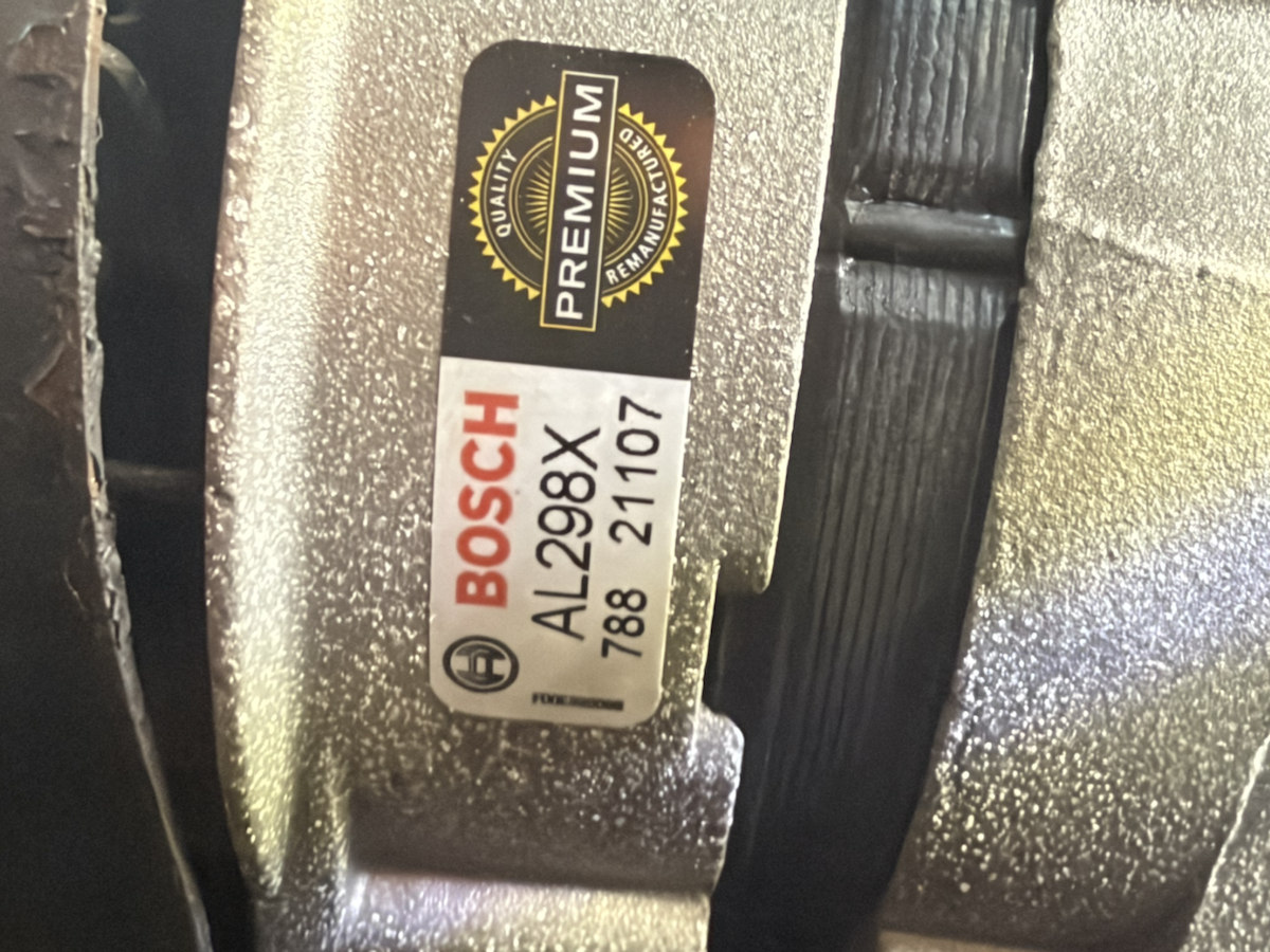
The fitted Bosch AL298X.
IMG_6976 identifies the alternator installed on this car as a Bosch Premium remanufactured AL298X. That gives us a real part number to research and compare. It does not supply the mounting-ear dimensions, installed pulley offset, wiring positions or a safe bolt-removal path.
The Bosch product listing specifies 12 V, 35 A, internal regulation, an external fan, plug type 110 and a single V-belt type for AL298X. Bosch lists the remanufactured unit without an included pulley. The car photos show a front fan and pulley, so identify and measure this installed pulley separately before ordering. Bosch does not publish a dimensioned mounting drawing on that accessible page.
Look at the installed assembly
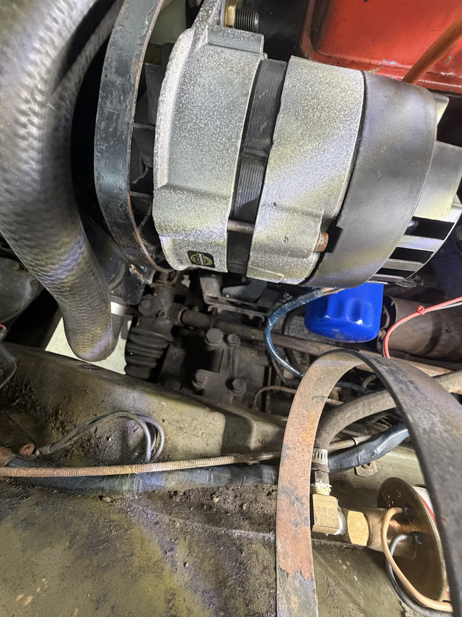
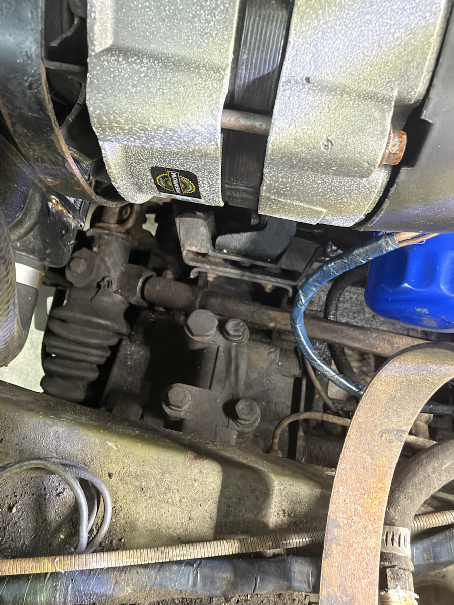
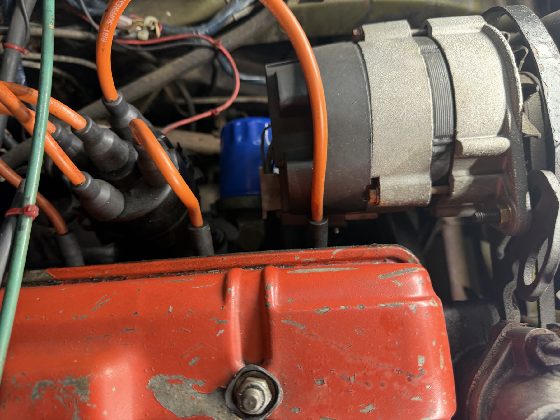
Specifications versus measurements
| Question | Evidence today | Needed before replacement |
|---|---|---|
| Electrical rating and regulator | Bosch lists 12 V, 35 A, internal regulator, plug type 110. | Photograph the actual rear terminals and each wire. Confirm the replacement’s terminal layout and electrical specification against the fitted car. |
| Fan and pulley | Bosch lists an external fan and 1V belt type, but says pulley not included with the catalog unit. A fan and pulley are visible on this car. | Measure the installed pulley outside diameter, groove profile, axial offset and shaft/nut stack. Check whether a candidate replacement includes a pulley or requires transfer. |
| Mounting | IMG_6971–6972 show part of the lower area. The current CAD uses Midget 1500 bracket and bolt catalog comparisons. | Measure both ear thicknesses, the gap, hole diameters, adjusting-link slot and pivot-bolt head/nut direction on this unit. |
| Clearance | The virtual 127 mm bolt sweep clears the modeled parts only. | Measure straight bolt-withdrawal space against the real distributor, vacuum unit and bodywork before loosening it. |
| 3D case shape | The STEP now follows the visible silver–dark–silver–dark layering in IMG_6972. | Measure case diameter and axial break positions. The current sections are photo-based estimates, not an AL298X machining drawing. |
The J&N 400-30029 listing cross-references AL298X but describes a different replacement unit. It warns that its 17 mm shaft will not accept an OEM pulley with a 15 mm bore. Those are dimensions of the J&N comparison, not measurements of this Bosch alternator; the warning is a reason to verify any proposed pulley transfer.
Capture the missing measurements
- With the engine off and unable to start, photograph the front face square-on, the rear electrical side, both lower ears and the upper adjusting link. Include a ruler in the same plane as each target.
- Record case outside diameter and the axial length of each visible silver casting, dark stator band and dark rear cover. Mark the planes used for each measurement.
- Measure the ear gap, both ear thicknesses and pivot hole diameter; photograph the bolt head, nut, spacer and washers before disassembly.
- Measure the pulley outside diameter, groove width and pulley-groove plane relative to the front mounting ear. Compare crank, pump and alternator groove alignment on the car.
- Record available straight space for the pivot bolt to withdraw in its actual direction, including nearby obstructions.
- Photograph the rear terminals before disconnecting the battery or wiring. Enter the values and image filenames in the planner evidence log.
