NORTH AMERICAN ARCHITECTURE / ESTIMATED REGISTRATION
Current revision: paired casting and external coolant-port boundaries ↓
Current revision: air-temperature compensator and factory check ↓
Connect the intake.
Latest: compare the rebuilt cleaner casing ↘
Earlier: compare the photo-estimated intake pose before and after ↘
The cleaner, carburetor and inlet manifold need distinct mounting faces. The earlier reference buried its nominal manifold flange inside the collector and overlapped the carburetor casting. This reconstruction adds an exposed neck, separate gasket and paired fixing roles, with coordinated component positions.
The factory supports the attachment roles and quantities. All new outlines, dimensions, hole positions, gasket thicknesses and installed coordinates remain estimates. A connected drawing does not verify sealing, loaded support, working clearance or a replacement path.
Follow the attachment chain
| Relationship | Factory evidence | Inspect the reference |
|---|---|---|
| Head / inlet casting | Factory p65: single-carb NAS manifold and four head-side inlet mouths. Existing head-port and collector datums remain unregistered. | Casting · Head-side hardware evidence |
| Manifold / carburetor | p65: two 129383 studs. p124: one UKC490 gasket, two NH605041 nuts and two WL600051 spring washers. These are catalog roles, not fitted identities. | Gasket · Studs · Retainers |
| Carburetor / cleaner | p122: one 148006 gasket, two SH505071 screws and two WL600051 washers. | Gasket · Fixings |
| Cleaner interior / cover | Photo-supported separate case, cover and paired latch references with independently sized panel-filter comparison. | Cover · Latches · Element |
Current placement and mounting faces
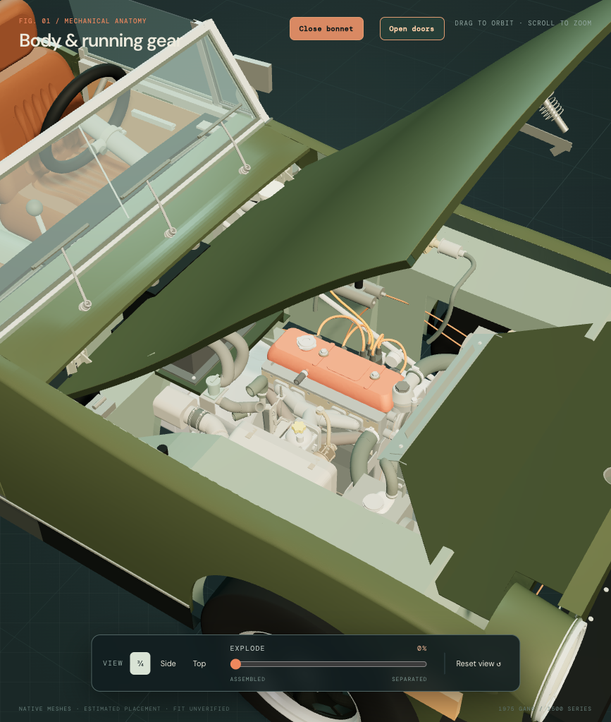
Relative to the historical engine-study intake, the current whole-car carburetor is 84 mm outboard, 5 mm down and 35 mm forward; the cleaner, filter, latches and inlet branch are 65 mm outboard with the same vertical and forward changes. The seven local throttle groups follow the carburetor. The latest change from the previous whole-car intake is 36 mm outward, 5 mm down and 35 mm forward, as documented in the photo-derived pose study below. These are conditional reference choices, not owner measurements. Carburetor sizes stay; the cleaner shell and relative placement are superseded by the later envelope revision below. The exposed manifold neck was rebuilt between the retained head-side branches/collector and the shifted carburetor flange. Engine/body placement, heater, wing and exhaust remain independent references.
The manifold neck reaches a reference face at X=−197 mm; the carburetor outlet face is X=−198 mm. The cleaner backplate face is X=−283 mm and carburetor inlet X=−282 mm. The drawing port center is Y=50 mm, Z=35 mm. Two 1 mm gasket roles close the reference intervals, without establishing fitted thickness, compression or actual machining/sealing faces. The simplified gasket outlines are not manufacturing tracings. Subsidiary passages in the 148006 supplier image remain unidentified and are not modeled as working circuits.
The common cylinder-head boundary
The whole-car head now has a local flat manifold-side port land and a separate common gasket role. The earlier rectangular casting extended into both manifold pad references. The supplier bare-head image supports a shared flat face; the factory p65 lists one GEG648 gasket.
In the native engine coordinate frame, the reference face is X=−87 mm over Y=1–74 mm and Z=−176–176 mm. The manifold pad faces stay at X=−88 mm, leaving a 1 mm gasket envelope. Every one of these stations and dimensions is a construction estimate. The original deck, top, opposite side, eight port centers and blind port-recess ends remain. This is a correction to the virtual casting, not a machining instruction for the car.
The selected Payen comparison photograph has four round and four separate rectangular windows. Ten subsidiary gasket apertures are shown at estimated positions without assigning them to fitted studs or dowels. Other gasket variants may join the center exhaust windows. Neither the outline nor its holes are a tracing, drilling template or fitted gasket identification. Head-side studs, clamps and the inlet-to-exhaust attachment remain unresolved.
Supplier bare-head comparison · Payen gasket comparison. Neither identifies what is fitted to this car.
Use in a workshop study
Select or isolate the casting, carburetor, backplate, gasket and fixing groups to understand which components attach to which faces. General separation moves this chain with the engine as an inspection convention. It does not release fasteners, operate the throttle, disconnect hoses or prove an extraction trajectory. Local throttle geometry does not trace the remote pedal/choke cables.
The twin-SU spacer/gasket arrangement is a different configuration. The factory also lists a TKC1990 heatshield; the supplied views do not establish its fitted shape, attachment or installed pose, so this study does not insert a guessed shield into the car. Complete fuel, breather, vacuum and temperature-control traces, actual fastening maps and the applicable North American workshop removal/refitting procedure remain unresolved. The available UK maintenance illustration of two round air cleaners is not used as this case's service procedure.
The revised reference head no longer overlaps the two manifold pad groups. Inlet-to-exhaust and body contacts remain source comparisons. Refer to the whole-car evidence register for the current limited contact checks. No zero-contact result establishes fitted clearance or safe operation.
Sources and native geometry
Factory manifold plate p65 · Cleaner plate p122 · NAS carburetor fittings p124 · Supplier 148006 comparison image.
Earlier intake-pose stage
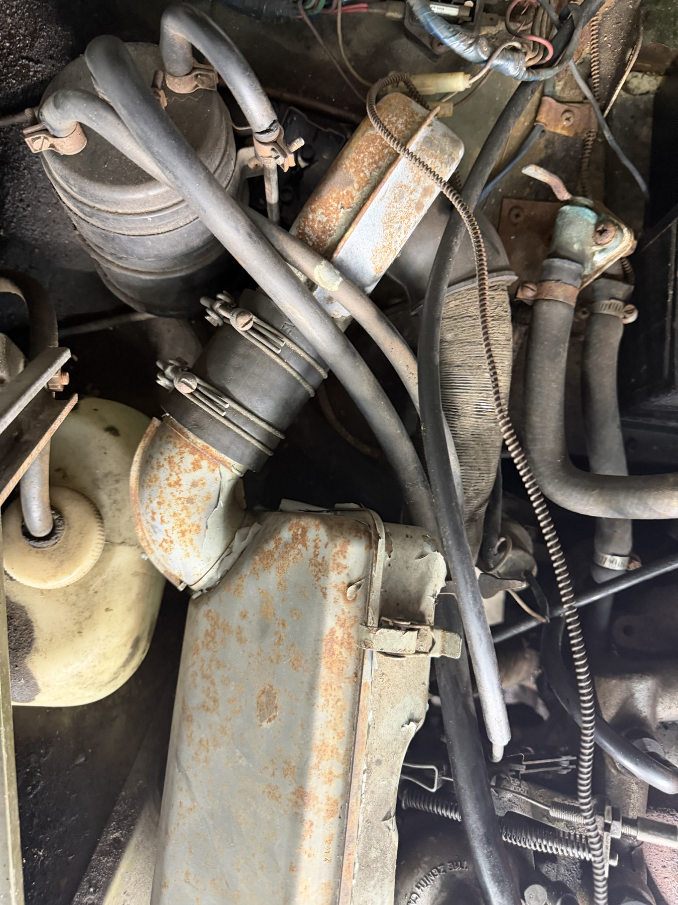
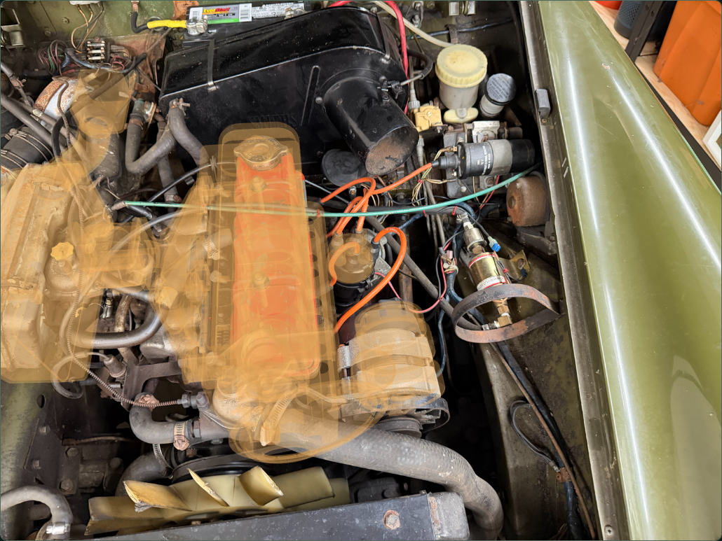
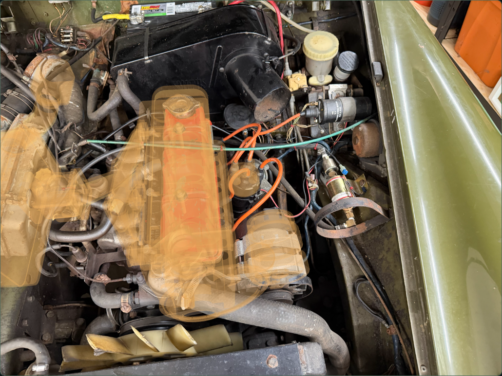
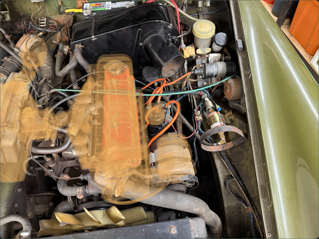
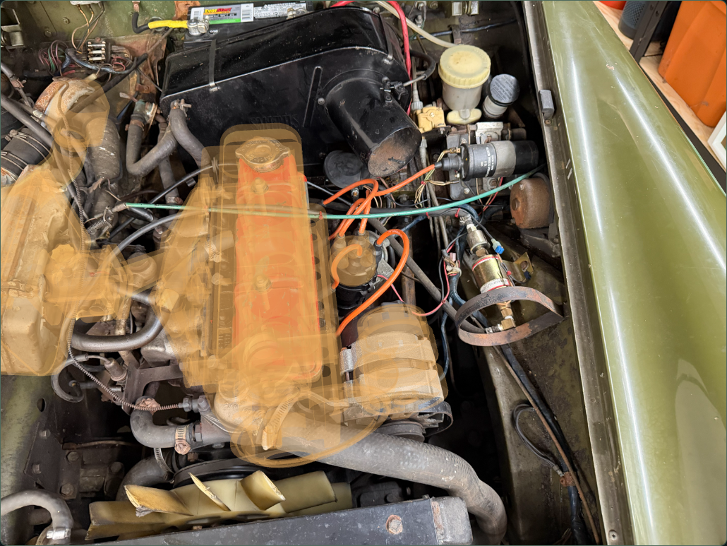
The old carburetor cap lay well away from the visible yellow cap in the shared photo frame. Three registered views now triangulate the yellow-face center proxy. At the existing provisional engine scale, the selected whole-intake translation is 36 mm outward, 5 mm down and 35 mm forward. These are rounded drawing changes, not owner measurements or fitted mounting coordinates.
Keep the assembly connected
The carburetor, cleaner, two gasket roles, studs, nuts, washers and screws move together. All seven local throttle-control groups follow the same translation. Their individual sizes and internal relationships stay. The head-side manifold branches, common head/manifold gasket and head port land remain fixed; a revised oblique neck joins those branches to the new carburetor flange.
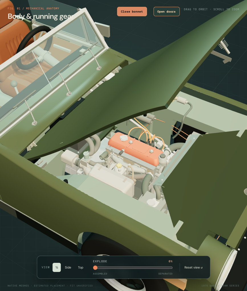
Evidence and limits
The face-centroid observations come from IMG_6854, IMG_6855 and IMG_6856. The engine frame inherits the unmeasured 152 mm cover-stud spacing and interpreted cap-face roll used in the native/photo comparison. Withholding one view gives about 0.94 to 5.15 analysis pixels of discrepancy. Shared cameras, approximate centroids and unknown cap/neck dimensions prevent treating that as independent dimensional accuracy.
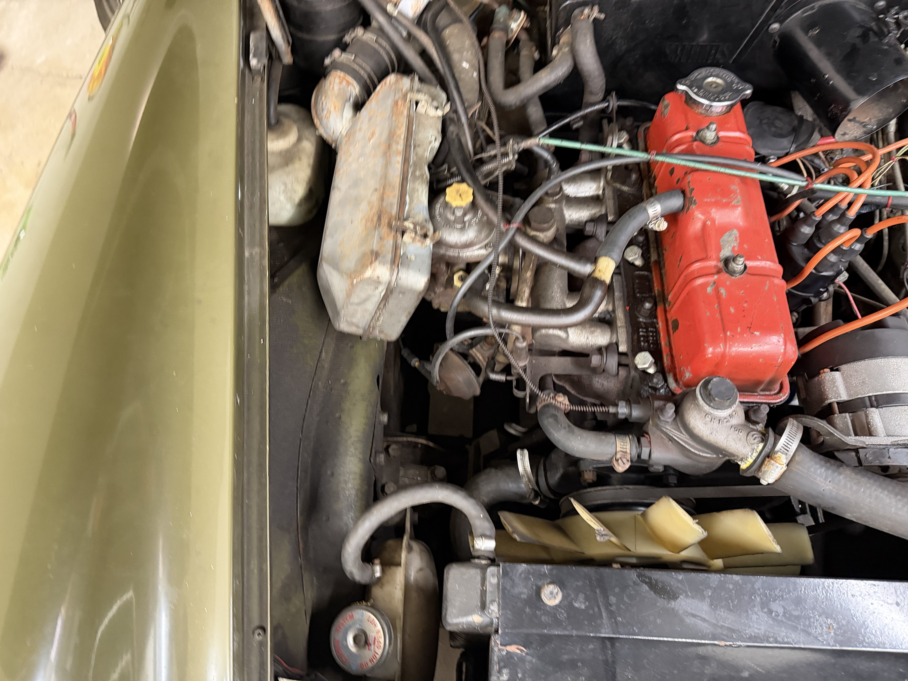
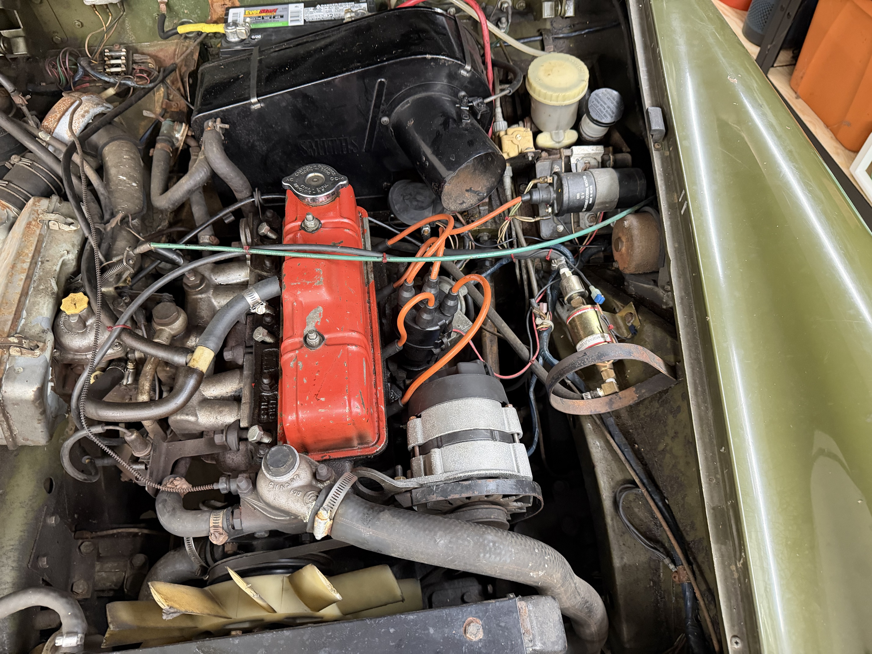
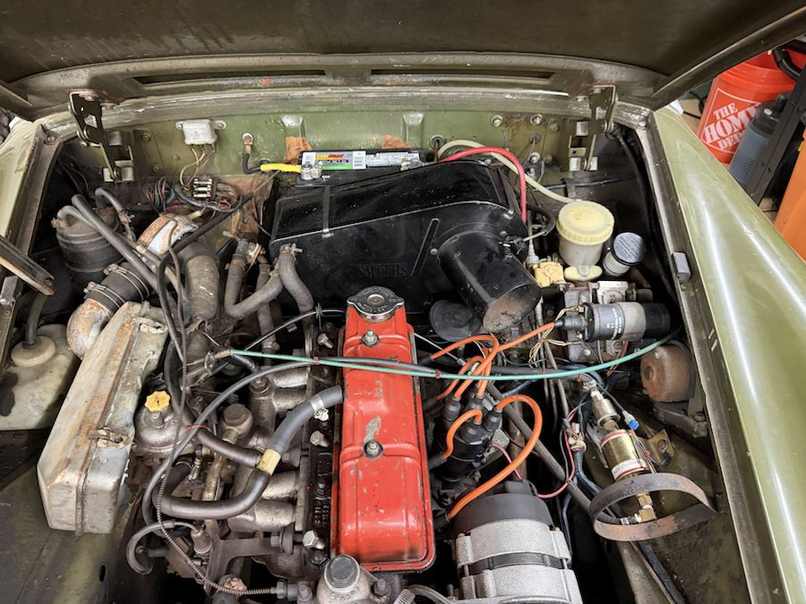
All 79 native solids remain valid. Twenty-six component groups retain native volume and bounds under the same translation; the two fixed head-side mesh payloads remain identical. Source checks confirm the open neck centerline, local fixing passages and no positive manifold overlap with the sampled head/carburetor solids. These are reference topology checks, not fitted clearances or operating flow.
The cleaner dimensions, relative case/port layout, bracket and flange sections remain estimates. The engine/body frame stays unchanged. Complete remote fuel, breather and accelerator routes remain untraced; no route is stretched to invent an endpoint. The detailed engine study retains its historical intake pose. Separation is illustrative: gasket seating, threads, torque, return action, body clearance, tool access and an applicable removal sequence remain unverified.

Rebuild the cleaner around visible surfaces
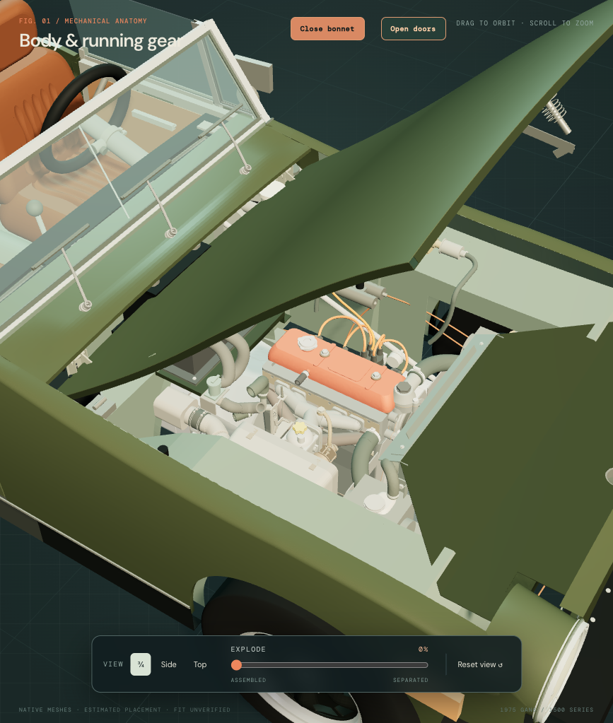
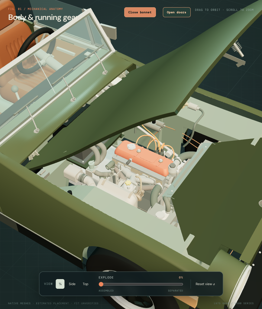
The previous case extended too far forward in the registered bay comparison and had a low, shallow shoulder. Existing reconstructed features on the front lip, rear upper corner and lid shoulder now guide a shorter, asymmetrically rounded shell. The selected reference envelope is 100 × 160 × 250 mm: width remains an estimate; the lower boundary stays; the front/back and upper seam are rounded photo-conditioned choices. All millimeters inherit the provisional 152 mm engine stud span, so these are not fitted casing dimensions.
The carburetor face and paired fixing axes remain fixed. A 15 mm reference backplate depth replaces the earlier 25 mm choice. A sloping lid shoulder joins the retained outboard reference; two formed retaining-strip roles follow it. The inlet bend, sleeve, chamber and clamp references move 15 mm rearward together to follow the new rear wall and its open passage. Their dimensions, actual circuit and working mechanism remain unverified.
Keep the filter uncertainty visible
The independent 250 × 120 × 30 mm filter comparison retains its dimensions and moves only to the revised case-relative station. It intersects the new casing reference. This source conflict could reflect the conditional scale, shell interpretation, filter outline, size or station; it does not prove interference on the actual car or identify a compatible element. No dimensions are reduced to force a fit.
The filter comparator stays out of the assembled view until selected. Select or isolate the unfitted filter comparison to inspect that discrepancy. The current casing is a photo-led reference; the detailed engine study retains its earlier case/element comparison. No seal compression, latch engagement, cold-air circuit, fitted clearance or verified filter/case removal path is established.
What was checked
The 29-group export has 73 valid positive solids. Twenty carburetor, manifold, head and fixing mesh payloads remain identical; 147 other native geometry files stay. The carb attachment, paired mounting bores and rear inlet passage remain open. Mesh/native volume agreement, retained filter dimensions and changed source contacts are recorded. The selected source points sit closer to the new shell, but those same observations guided the shape: that comparison is construction evidence, not independent dimensional accuracy.
Replace the short center with the manifold’s paired architecture
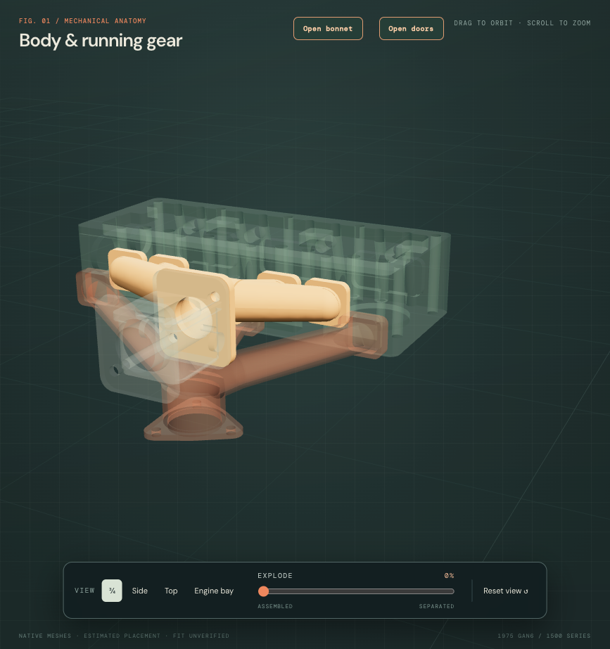
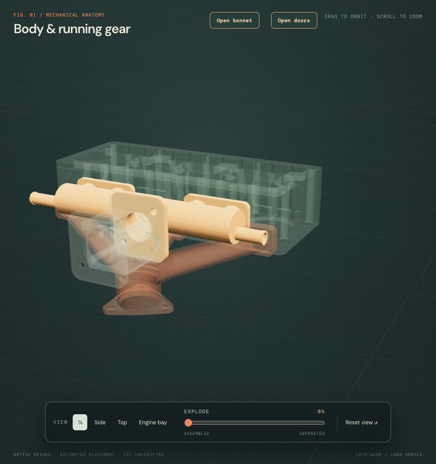
The former reference used four diagonal runners converging on a short center. The current manifold follows a more specific TKC285-family donor comparison: paired head flanges, a longitudinal collector and two axial end spigots. This changes the main casting envelope rather than shifting the carburetor or head to make the assembly appear connected. The four head-mouth centers, nominal mouth radii, head/carburetor mounting planes, carburetor, cleaner and body poses stay. All28 other intake meshes remain byte-identical.
Evidence and branch limits
Factory plate65 distinguishes the TKC285 USA/Canada single-carburetor manifold from RKC723. A TKC285-labeled donor listing and its casting photograph show the paired flange and long-collector architecture, together with two axial end spigots. This is an unscaled supplier comparison, not identification of the manifold fitted to this car. Existing owner photographs establish the single-carburetor assembly and surroundings; they do not expose or dimension these hidden features. RKC723, later and California arrangements remain distinct.

The new266 mm collector length, paired flange plan, runner profiles, spigot projection/diameters, beads and all air sections are construction estimates within the existing source frame. The donor image does not provide a calibrated scale, hidden core section, actual tube/casting joint or end orientation. The separate159942 emissions-adapter role is not assigned as a coolant connection.
External ports without an invented internal waterway
The end-spigot bores stop at declared unmodeled inner boundaries near the collector caps, before the estimated air cavity. Those boundaries are reconstruction omissions, not actual blind coolant ports or plugs. No internal coolant channel, flow direction, thermal behavior, gallery capacity or pressure integrity is reconstructed. One selectable native solid does not establish whether the actual spigots are integral, pressed or otherwise attached.
The retained return-pipe/cuff and pump-end adapter are not moved or stretched to meet the new reference ports. The corresponding drawing endpoint separations are approximately94.80 mm and85.05 mm; they are distances between unregistered source points, not actual hose lengths or nearest physical clearances. The pump housing’s shared registration and the manifold/pipe hose branches still need evidence.
Validation and the remaining exhaust conflict
Native checks cover29 groups and73 valid solids. Only the manifold mesh changes; all28 other meshes and their checked native volumes stay. Four head mouths and the carburetor mouth remain open, and wall/bore probes inspect both end-spigot references and their explicit inner boundaries. The manifold mesh/native volume difference is approximately0.066%. These are construction checks, not evidence of fitted port matching, seal performance or a correct internal section.
The checked head, gasket, carburetor, local fixing and cleaner comparisons have no positive source overlap with the manifold. The retained exhaust reference still conflicts: its sampled intersection changes from approximately2357.29 mm³ to2641.41 mm³. That source discrepancy is reported without moving the exhaust, head or intake assembly to erase it. It is not a physical interference finding on the car. The photo-bay overlay updates only this casting mesh and retains44 other meshes.
Workshop boundary: the paired casting and external ports make the support and hose-connection relationships easier to inspect, but they do not establish a safe release order, fitted hose assignment, tool access, support arrangement or withdrawal path. The accessible AKM4071/B segments omit the USA manifold/exhaust pages130–132. UK instructions are not substituted for the USA single-Stromberg procedure. Earlier mounting and photo-pose sections describe retained stages; this section supersedes their earlier branch/collector shape.
The cleaner branch has a temperature-control reference
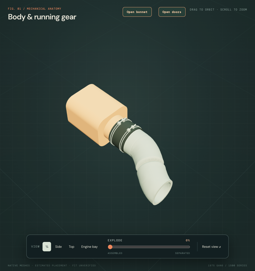
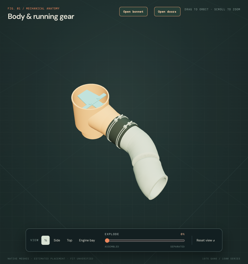
The former chamber was an open rectangular box with an unassigned rear boundary. The current reference supplies the rounded body, circular ambient-air opening and perpendicular open duct neck identified by the factory air-temperature-control arrangement. The cleaner-side neck retains its previous axis, mouth and annular material. Elbow, rubber sleeve, wire clamps, cleaner, carburetor, manifold and body placements stay.
Factory Midget role, with an attributed component comparison
Factory plate122 lists BHH1163 as the North American air-temperature compensator, CHA379 as the cleaner connection and CHA491 as the Federal preheater connection. These are documentary roles, not identification of the assembly currently fitted. Owner IMG_6885/6886 and the supplied7034/7035 views show the local chamber, sleeve and clamp context but do not dimension hidden connections or identify the mechanism’s condition.
The MG Car Club’s photographed BHH1163/CAM2864-family component shows the circular opening, plate, bracket and two visible fastening heads. Its installation is an MGBGTV8 comparison. No MGB duct dimensions, fitted configuration, adjustment method or temperature setting is applied to this Midget.
A documented check, without simulated thermal behavior
AKM4071/B, printed105, operation17.30.02, was visually read in the1975–1976 emission-control section. The factory check compares the plate blocking the ambient intake when cold with its movement toward the hot-air hose as the engine warms. That establishes the roles of the two air entries; it does not dimension the housing or calibrate this model.
The optional plate/bracket stays at one arbitrary inspection pose. It is hidden in the ordinary assembled display and becomes visible when selected. No fitted mechanism state, bimetal construction, working pivot/mount, thermal movement, switching temperature, air mixing or operating performance is reconstructed. The factory check is not a verified removal/refitting procedure or withdrawal path for the actual car.
Which connections are represented
The retained cleaner-side mouth is at source X−300/Y50/Z−247 mm on the existing +Z axis, with the inherited24/20 mm outside/bore radii. The new circular opening at X−300/Y84.5/Z−321 mm and32.5 mm radius is an estimated ambient-entry reference. The perpendicular duct mouth ends at X−300/Y−10/Z−321 mm on an estimated−Y axis, using a24/20 mm outside/bore comparison. These are drawing coordinates and construction sections, not owner measurements or factory dimensions.
The hot-air neck stops open and unassigned. No hose is stretched to an exhaust shroud, and no CHA323/California CHA503 preheater, actual Federal/California branch or complete warm-air route is selected. The cup, shoulder, rim, wall sections, plate shape/thickness, bracket, rivet envelopes and port directions remain estimates. The plate’s true attachment and loaded contact with the housing are unresolved.
Scoped validation and remaining gaps
The compensator-stage export contained30 native groups and76 valid solids. One existing chamber mesh changes, one optional plate/bracket group is added, and28 meshes remain byte-identical to the preceding revision. Head, carburetor and manifold interface metadata stay. Both new entry references and the held cleaner-side neck pass open-bore and wall probes; zero original cleaner-neck material is lost. Mesh/native volume differences are below0.11%.
The checked elbow, sleeve, wire clamps, cleaner cases, manifold, exhaust and block source comparisons have no positive contact with the revised body; the fixed plate also has no positive body intersection. These checks establish this static construction only. They do not verify the fitted chamber, rubber deformation, thermal or body clearance, support, sealing, pressure behavior or a service path. Earlier29-group validation records describe the preceding stage; the current record below covers this revision.
The rocker-cover outlet now follows the owner photographs
The earlier model put the cover outlet behind the rear hold-down station and ended its hose as a straight stub. Three existing owner views support a substantially more forward station. The current reference moves the outlet and clamp107 mm forward in the conditional engine frame, restores the sheet wall at the old outlet, and adds the curved local hose through the visible yellow-wrapped junction station. Head, manifold, carburetor, cleaner, cover roof, filler and hold-down geometry retain their previous positions.
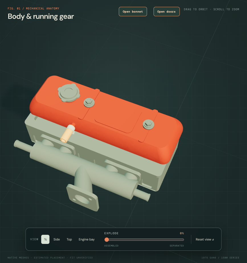
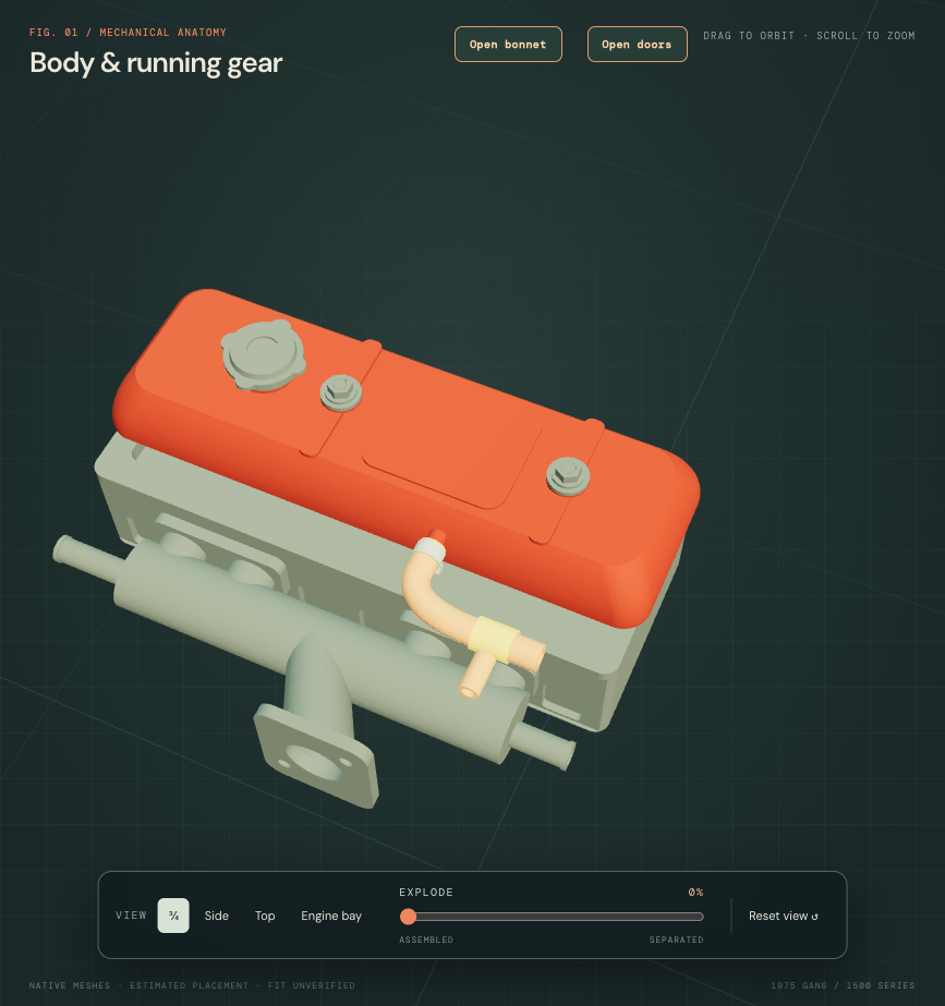
What the photographs support
IMG_6854, IMG_6855 and IMG_6856 show the clamp, curved trunk and wrapped junction. Reusing the existing registered cameras places the visible clamp-surface proxy near source Z51.5 mm and the wrap proxy near Z111.2 mm. The clamp and wrap picks reproject within approximately2–6 source pixels across those views. They are surface picks, not measured mechanical axes.
The photo scale still depends on an unmeasured152 mm stud span and assumed cap-face orientation. The outlet therefore uses rounded Z52 mm while retaining its inherited estimated X−55/Y109 mm root and −X direction. The visible clamp proxy’s Y119.9 mm does not establish the neck-axis height. The wrap uses rounded X−107/Z111 mm with the retained Y109 mm drawing plane. No owner measurement or fitted positional tolerance is claimed.
Two attempted picks on the smooth front loop and carburetor-side occlusion boundary disagree between views, with reprojection errors up to33 pixels. They are recorded as rejected 3D correspondences. The full front loop is consequently not reconstructed from those points.
External connection, with explicit evidence boundaries
The inherited11 mm metal neck,7.6 mm display bore,17 mm hose outside diameter,7/16-inch replacement-hose bore comparison and clamp geometry stay. Only the cover outlet’s fore/aft station changes. The new hose has an estimated smooth bend, continues through an estimated wrapping sleeve and stops at an open forward boundary. A short side-leg reference stops outside the wrap; its hidden seat and distant end remain unassigned. Its section and direction are drawing estimates.
The wrapping is modeled only as an exterior sleeve. It does not establish a hidden T-piece, restricted orifice, valve, material, flame trap or internal flow connection. No hose is forced onto the carburetor or canister. The open modeled ends are omissions, not proposed cuts, fitted disconnect locations or actual open hoses.
Factory context and workshop limit
AKM4071/B, printed102, drawing17.00.01 [75–76], was visually examined. Its1975–1976 emission-control key distinguishes the cover ventilation, purge line, restricted connection and oil separator/flame-trap roles. It supplies system context without identifying the wrapped component on this car or assigning its hidden branches. This drawing is not a verified hose-replacement procedure, release order or withdrawal path. Missing applicable US manual sections remain recorded; no UK procedure is substituted.
What was checked
All30 preceding intake meshes remain byte-identical. Five new valid reference solids supply the cover, clamp, curved trunk, wrap and side leg; the main viewer omits the three superseded historical cover/stub/clamp meshes. The cover is unchanged outside the two local outlet regions. The new neck passage and both trunk boundaries are open, and the hose, clamp and cover have no positive modeled material overlap. Checked contacts with the retained head, manifold and carburetor are zero. These are construction checks, not fitted-clearance or sealing results. Mesh/native volume differences are below0.11%.
The whole-car viewer and photo-bay comparison use the same revised engine-frame geometry. The separate engine-only study retains the historical outlet and stub for comparison. The following loop section supersedes this short forward boundary. Its hidden return and remote connection remain unresolved.
The visible forward breather loop is now represented
The first breather revision corrected the outlet and stopped shortly beyond the wrapping. The current reference extends the hose around the visible forward run beside the intake, using the existing owner photographs. The cover, neck, clamp, wrap, side-leg reference and all surrounding intake meshes stay. The return toward the carburetor still ends before its uncertain hidden connection.
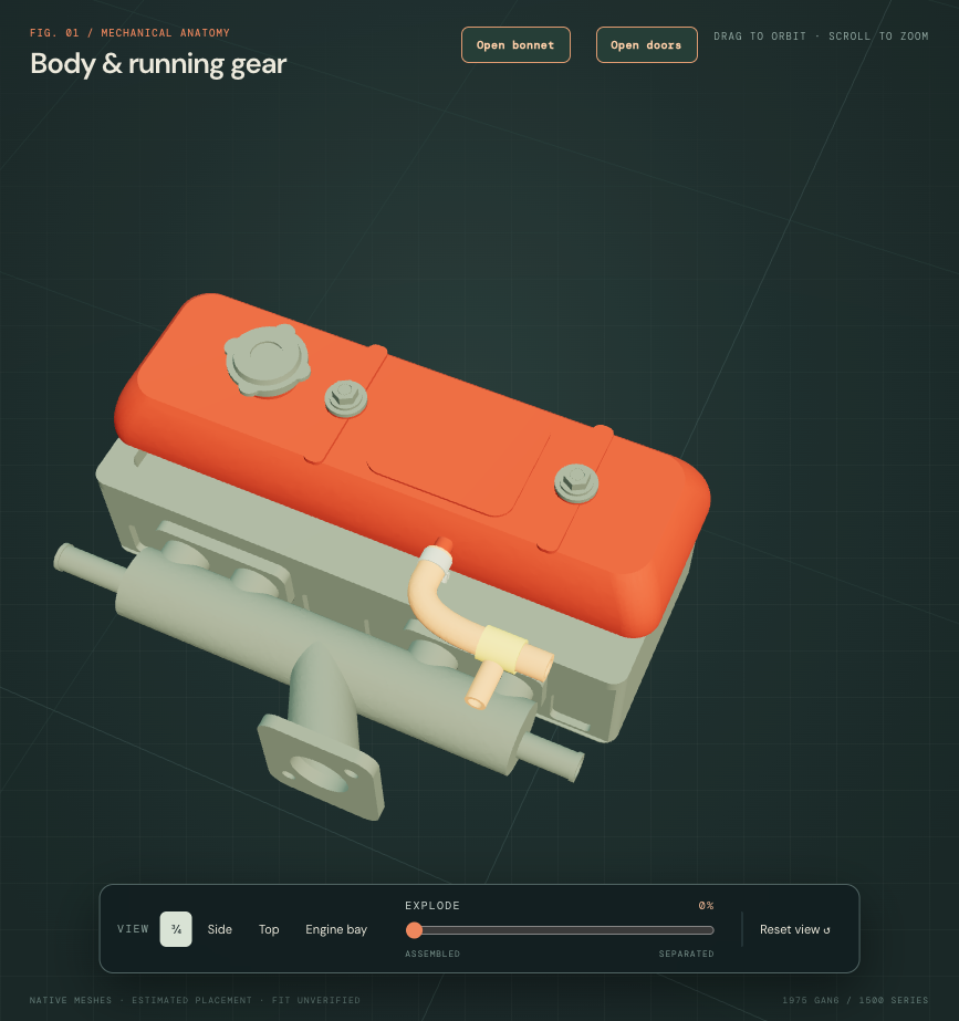
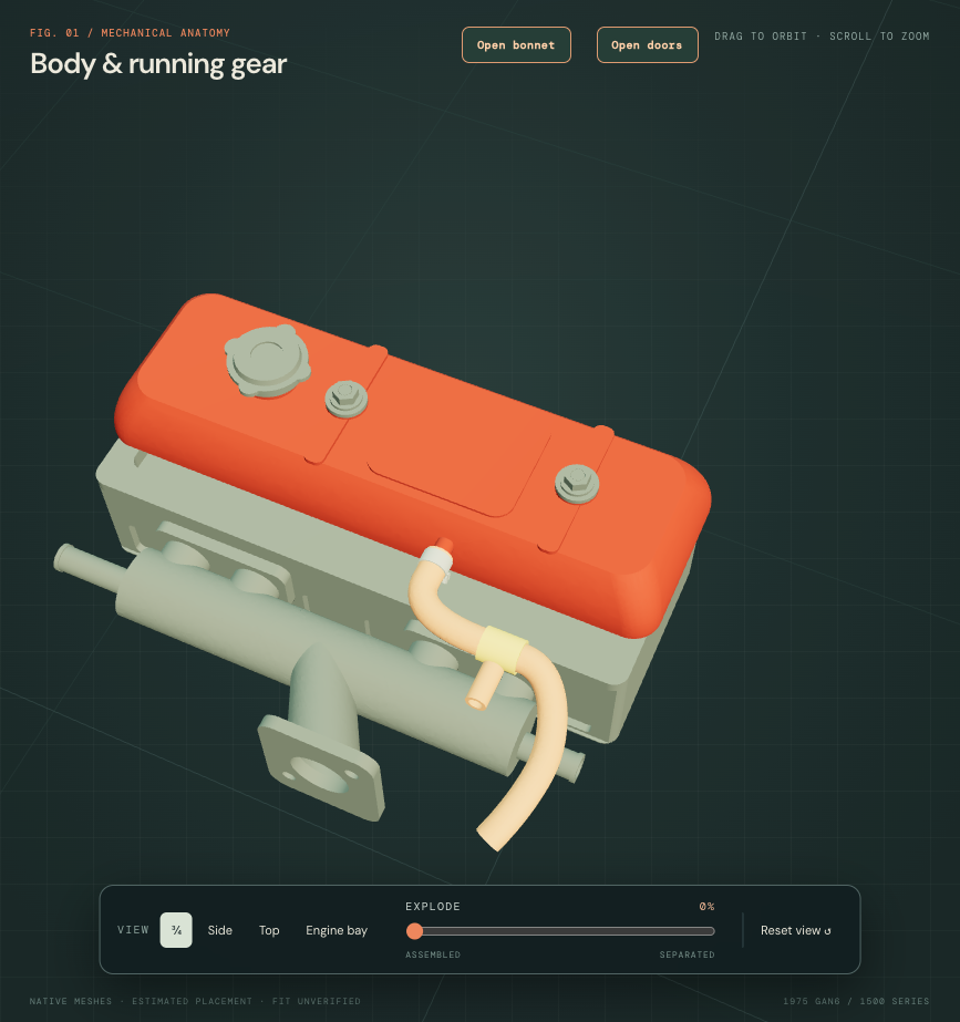
Curve evidence, without false point matches
The observations follow the visible hose centerline independently in IMG_6854, IMG_6855 and IMG_6856. Samples in separate photographs are not treated as the same physical points. A smooth reference curve can slide along the secondary image observations while retaining their order. This replaces the failed isolated-point interpretation recorded in the earlier section; those rejected point matches remain rejected.
The wrapping front plane and initial forward tangent retain the previous construction. The far boundary stops at the shortest common view coverage. The unsupported tail of the fitted curve is discarded; no hose is stretched onto a carburetor port. Only the hose mesh changes;34 other intake meshes remain byte-identical.
What remains estimated
The shared camera registration still depends on an unmeasured152 mm rocker-stud span and interpreted cap-face orientation. The fitted curve has median image discrepancies of approximately4–5 source pixels in the two large photographs and1.3 pixels in the smaller view, with maxima of16.2 and3.5 pixels respectively. That describes image agreement, not millimeter accuracy. Changing the smoothing weight changes the retained curve by up to5.5 mm in the conditional frame; this sensitivity is not an uncertainty bound for the actual car.
The added curve represents approximately122 mm of centerline at the current assumed scale. That is a drawing extent, not a replacement-hose cutting length. The inherited17 mm outside diameter and7/16-inch replacement-bore comparison stay. The hidden curl, carburetor-side seat and port identity, side-leg destination, junction internals, fitted hose length, sealing and operating clearance remain unresolved.
A documented inspection scope
The accessible 1975–1976 U.S. maintenance summary, printed40, and printed42 maintenance continuation were visually examined. They call for inspecting breathing and evaporative-system hose security and, in the later service listing, checking hoses, pipes and restrictors for blockage and condition. These are applicable documentary inspection roles. The model helps locate the visible cover connection, bend and wrapping region; its open reference bore does not establish that the real hose or restrictors are clear.
The maintenance text does not dimension the route or supply a verified release sequence for this car’s modified system. No pressure test, cutting instruction, clamp setting, replacement compatibility, canister/carburetor connection, or removal path is inferred. Inspection separation remains illustrative.
Validation and the next substantial priority
The extended hose is one valid hollow solid, has open socket and terminal boundaries, and retains a continuous drawing connection through the wrapping. The conditional curve’s minimum centerline radius is approximately24.7 mm; that supports this undeformed tube construction, not a fitted bend specification. Mesh/native volume difference for the hose is below0.09%. No positive material intersection appears against the retained cover, clamp, wrap, head, manifold or carburetor source checks. None of those surrounding parts moves.
The next priority is the unresolved engine-side support/drive relationships or another supported major bay connection. This loop’s hidden return and side-leg destination remain precise evidence gaps rather than reasons to halt independent work.