Map the manifold fixings
before planning removal.
The head’s reference port layout now has four inlet and four exhaust mouths. That does not establish the fitted fastening stack. The head-to-manifold studs, clamps, washers and nuts are absent from the current engine mesh; the vertical cylinder-head studs shown elsewhere retain the head to the block and are different hardware.
The factory engine-unit plate MB0704, PDF p. 65, printed 107-B93/94 separates the head-side clamps from the inlet-to-exhaust attachment. The Moss manifold plate, printed p. 29 gives the two head-side stud lengths. These identify reference hardware, not the pieces currently on the car, their fitted locations, threads, engagement or tightening procedure.
Keep four joints separate
On narrow screens, scroll the tables sideways to read every source detail.
| Joint | Reference relationship | What to capture on this car |
|---|---|---|
| Head to manifolds | Catalog comparison: eight studs, six clamp pieces, eight plain washers and eight nuts in two nut forms. | Each actual stud position and complete stack, including any missing or changed hardware. Do not assign a clamp or nut to a station from matching quantities. |
| Inlet to exhaust manifold | Factory items 10–14 separately list two BH505131 bolts, two WF8 washers, one TD861 stud, one WL208 lock washer and one HN2008 nut. The stud/nut arrangement is marked USA/Canada to 1977. | The actual connection and every fastener, with a side view of its seating faces. These are additional attachments, not part of the head-side nut count. |
| Carburetor to inlet manifold | The USA/Canada-to-1977 branch lists two 129383 carburetor studs; the plate also depicts a different twin-carburetor branch. | The fitted single-carburetor flange, spacers, gaskets, heat shielding and fixings. Keep the air-cleaner inlet sleeve’s unidentified remote end separate from this joint. |
| Exhaust manifold to downpipe | A separate flange and gasket. The current CAD has a three-hole GEG742-style comparison. | The actual flange, fastening count, clocking, gasket and tool approach. Its fasteners do not belong to the head-side clamp inventory. |
Head-side catalog inventory
The factory plate supplies the clamp, washer and nut counts below; the Moss comparison supplies stud lengths. Lengths are overall catalog lengths, not exposed projections or measured thread engagement.
| Reference item | Catalog quantity | Source detail |
|---|---|---|
| Long head-side stud | 6 | Moss 328-650 · 1⅞ in overall (47.625 mm). |
| Short head-side stud | 2 | Moss 328-660 · 1⅜ in overall (34.925 mm). |
| 137845 clamp | 2 | Factory item 16. Shape and fitted pairing need inspection. |
| 58258 clamp | 4 | Factory item 17. Keep both clamp forms distinct. |
| WP36 plain washer | 8 | Factory item 18. |
| 100498 nut | 6 | Factory item 19. |
| CHA360 manifold clamping nut | 2 | Factory item 20; Moss separately lists two long nuts. Fitted form and station remain unverified. |
Do not infer the stack from counts. Six clamp pieces and eight stud/nut positions do not tell you which fitted location uses each form, whether a washer bears on a clamp or casting, or which studs carry the longer nuts. No head-side fixing coordinates have been assigned to the CAD.
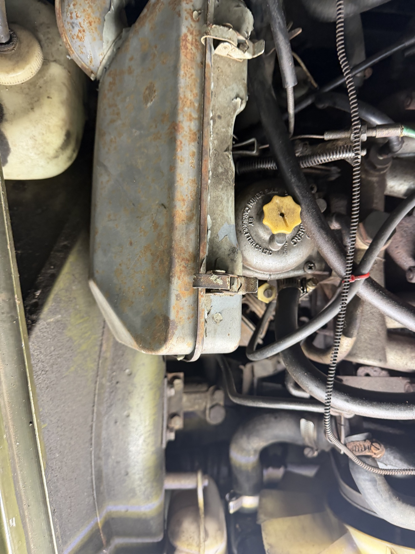
Record the other connections too
The factory plate also lists a coolant-return pipe (212935), inlet hoses (149699) and a USA/Canada EGR pipe/valve group. These are separate from the mechanical fixing counts. Trace the actual coolant and emissions plumbing, controls, shields and supports attached to the fitted assembly. The four-joint map is not a complete removal sequence or proof that those connections are present, clear or disconnected.
Open inlet reference, unresolved mounting
The CAD inlet manifold now has four head-side openings and one carburetor opening in a connected casting reference. Their shapes, wall sections and positions remain estimates. Current exports also audit the exterior to distinguish the five intended mouths from unintended openings at runner transitions. Older open-manifold exports lack that check and may retain transition gaps. The five mouths belong to this limited passage reference; auxiliary ports and water-heating passages remain unmodeled. Opening results apply only to their matching exported geometry; they do not establish actual casting dimensions, sealing or flow. The current model places the carburetor lip 20 mm beyond the nominal manifold flange plane, while the manifold mouth center is 12 mm lower than the carburetor axis. The nominal flange remains buried in the estimated collector, and the casting overlaps the head and exhaust study. These are reconstruction discrepancies, not measurements of this car or a gasket/spacer specification. The focused view shows the manifold with the carburetor; it cannot establish a fitted joint or removal path. During planned access, survey both joint faces, opening centers/profiles, the actual carburetor stud centers and every stack layer independently using named physical datums.
Connected exhaust reference, unverified fit
The exhaust study now opens four estimated rectangular head mouths into one downpipe mouth in a single casting reference. An exterior-opening audit checks those five mouths separately from the three stud bores and detects unintended openings. Its results apply only to matching exported geometry; older exports can retain solid branch placeholders. The head recesses remain blind, and actual internal turns, wall sections, auxiliary emissions connections and casting identity remain unverified. The downpipe aperture and hole pattern stay independent of the head mouths. Source downpipe/gasket planes coincide, but that does not establish flange bearing, gasket compression or sealing. The current reference still overlaps the head and inlet study; the normal transition material increases the inlet/exhaust overlap rather than resolving their guessed positions. Survey the actual head, inlet-to-exhaust and downpipe joints independently during planned access. No fitted port registration or removal path is established.
Survey each actual joint face independently
The current mounting conflicts need joint-face evidence. During already-planned access, the blank direct face survey can record actual opening shapes and fixing-hole traces without forcing a circle, rectangle or catalog count. Record one component and one joint face per survey; the head, manifold, carburetor, gasket/spacer and downpipe are independent sources. A gasket window does not establish a head-port divider.
- Identify the exact joint face and component marks, including unreadable marks. Declare a physical coordinate frame with fixed datums and its installed or removed configuration. A loose part on a bench does not retain its installed pose.
- Survey three ordered, widely separated face points and at least one unused plane-check point. Describe the positive-normal direction established by that ordering. Keep the same physical setup throughout.
- Trace only fully observed closed boundaries at that face with named, ordered 3D samples. Photograph reproducible sample locations and copy the boundary record for each opening, fixing hole or outer edge actually observed. Do not close a hidden outline by guessing or assume omitted features are absent.
- Measure at least two nonparallel sample-to-sample chord distances independently, using those exact named endpoints. Keep direct readings and their methods separate from distances derived from the coordinates. Survey the other mating component separately.
The analyzer reports independent plane and distance misses. Passing exports contain reference chords and check points, with no fitted solid or inferred curved profile; sparse straight chords are not the actual port outline. Optional registration requires separately checked physical/CAD datums and an exact target file. The result does not resize the engine, establish gasket contact or resolve a removal route. Open the export instructions below before entering readings.
Export checked reference geometry
From the project’s CAD directory with CadQuery available, save a completed copy as owner-face.json and run:
python build_manifold_face_survey.py --survey owner-face.json \
  --survey-comparison-limit-mm 0.2 --output-dir owner-face-reference
The value 0.2 is an example comparison limit, not a recommended accuracy or factory tolerance. Choose it from the actual survey method. Passing writes an evidence report and reference STEP in the named survey frame; failed comparisons write only the residual report. Use an empty output directory. Optional CAD registration needs separate named physical/CAD datums and its own comparison check; see the full CAD instructions for the format, limits and registration command. The worksheet is not an engine measurement-log import.
Compare registered samples with the model
The Measured joint references controls can show a completed survey’s sample points and straight chords over the exact model used as its registration target. Start there with Save original model JSON. Use that saved file and its fingerprint when completing the separate survey-to-CAD registration record; keep its named physical frame, configuration and independent checks. A STEP-target registration cannot be automatically reused for a different JSON target.
After both native comparisons pass, open the resulting manifold-face-report.json with Registered joint report. Frame reference centers the camera on the samples. The lines show through the model and remain separate reference geometry; they do not resize a casting, fill a face, infer an unobserved curve or establish contact or removal clearance. Accepted nonzero plane residuals stay in the displayed 3D samples.
The reference hides while related model parts are separated and returns with their assembled source positions. Changing model files clears it. A rejected report leaves any previous valid reference identified, and Clear reference removes the temporary drawing without changing saved notes. Keep all original files; references are local to the current browser session. See the complete registration and viewer instructions. The matching file fingerprint does not verify physical datum identity or turn a bench survey into an installed pose.
Make a fitted fastening map
- During planned access with the engine cold and unable to start, photograph the complete manifold side and then every visible fixing. Give each observed location your own stable label tied to physical landmarks. Record omissions and additional pieces rather than forcing the catalog count.
- For each location, record the stud, clamp, washer stack, nut form and seating faces as found. Photograph side-on views where possible. Note the tool approach and first obstruction without assuming that visibility establishes access.
- Keep exposed stud projection separate from removed overall length. Name the face used for a projection measurement. Record the removed stud’s thread identification and measuring method only when removal is already part of the repair; do not withdraw studs merely to fill this record.
- Keep the four interfaces in separate lists. Record installed and removed configurations separately, preserve source photos, and leave uncertain part numbers or counts unresolved. Use the applicable workshop and parts instructions after identifying the fitted assembly; this page provides no torque or removal sequence.
The blank record starts with no observed fixings. Copy its record fields once for each fixing actually documented. It is an evidence worksheet, not a CAD measurement-log import: it does not place studs, resize parts, certify thread engagement or establish a removal path.
New owner evidence · IMG_7034–7042
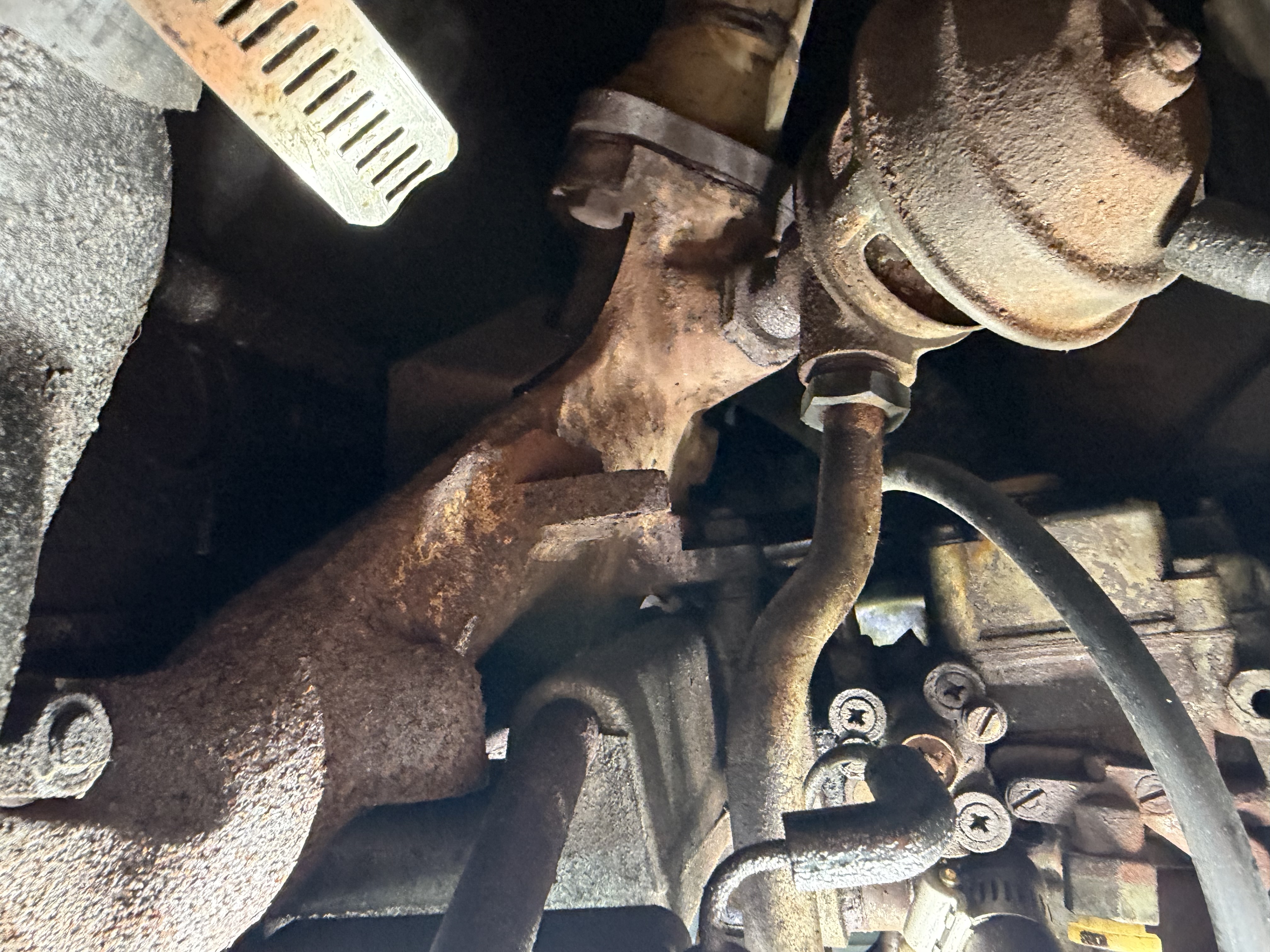
These views are integrated as direct visual evidence. They do not establish hidden thread or seal geometry, calibrated mounting coordinates, electrical compatibility or a verified removal path. Browse all nine new photographs ↗