Your 1975 MG Midget 1500 / air intake
Identify the air cleaner before choosing a filter.
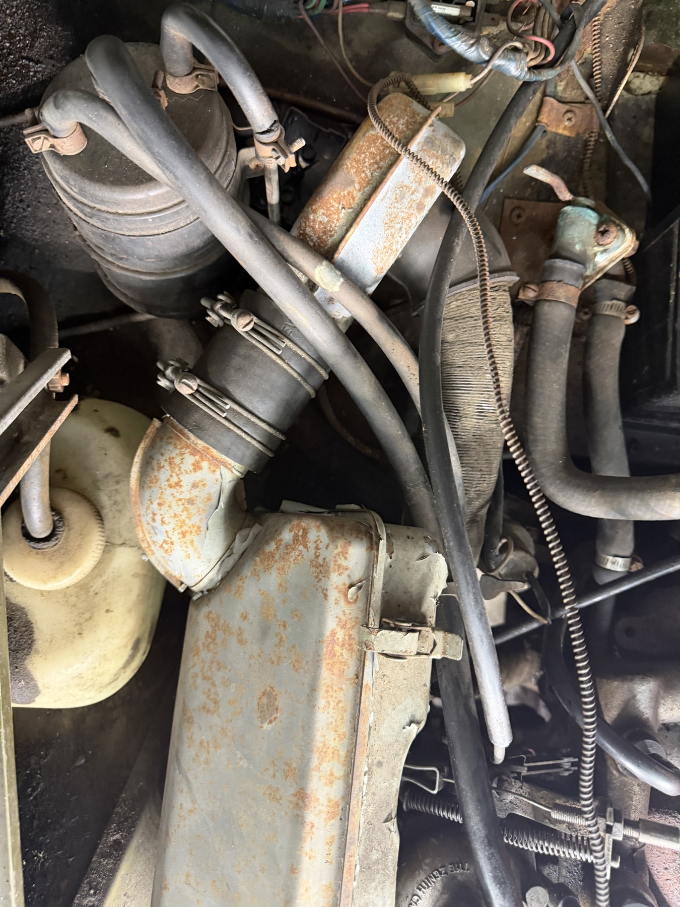
IMG_6885–6887 show the metal case, two external latches, a painted elbow, and a rubber coupling with two clamps. The case is rusted and its inside, element marking, seal, mountings, and exact dimensions have not yet been recorded.
What the sources establish
The factory North American parts plate (PDF p. 122) lists a 1975 cleaner assembly CHA295 and one GFE1060 element; it lists a different assembly from 1976. This identifies catalog candidates, not the unit fitted to this car.
The WIX manufacturer interchange (PDF p. 674) maps GFE1060 to WIX 42151. That is a useful search term when looking for an element, but it gives no confirmed dimensions or seal fit for this car. A published 29.7 × 28 × 4.8 cm claim conflicts with the long, narrow product image and should not be used to scale the CAD.
Our CAD case and filter are separate, selectable studies. The factory plate shows a vertical panel between an outboard cover and carb-side backplate. The CAD follows that order with provisional 100 × 150 × 280 mm case and 30 × 120 × 250 mm panel envelopes. The virtual latch release, outward cover movement, filter seat, elbow and coupling clearances are illustrative.
The available workshop scan shows two round air cleaners in its UK maintenance section (PDF p. 31). That is not a verified removal procedure for this North American rectangular case. Record how the fitted case opens before relying on a service sequence.
Make the next inspection useful
- With the engine cold and unable to start, take square-on photos of the whole assembly, both latches, the seam, mounts, elbow, coupling and each clamp. Include a ruler in the same plane as the surface being measured.
- Record any legible case, elbow, coupling or carburetor marks exactly as seen. A tiny mark near the seam in IMG_6886 is not readable enough to identify the assembly.
- Measure the complete case outboard depth, vertical height and long-axis length; note which face each dimension spans. Measure its distance to nearby parts separately so a future CAD build can check access.
- When the case is opened for service, document each latch before and after release, the cover’s actual movement, gasket position, inner seat, element orientation and any loose hardware. Photograph before cleaning or moving the element.
- Read every element marking, then measure the removed element’s long-axis length, vertical height, outboard thickness and seal lip. Compare its shape and markings with a supplier listing before ordering.
- Measure both metal tube outside diameters and the rubber coupling inside diameter, length and clamp positions. Check for corrosion, cracking and loose joints; keep the routing photo with the measurements.
Dimensions that would improve the 3D model
| Part | Record directly | What it unlocks |
|---|---|---|
| Full case | X outboard-to-carb-side depth, Y vertical height, Z long axis; note cover seam and measurement faces. | The CAD inspector accepts these three direct outside dimensions and can preview a resized case. Exporting the log can generate a separate owner STEP build. |
| Cover and clips | Cover outboard depth; lip and gasket section; both latch stations from one end; hook and pivot views. | A real split line, latch geometry and a removal path. The current virtual motion is not validated. |
| Filter and seat | Element length, vertical height, outboard thickness, marking and seal location; inner case opening and seat dimensions. | Direct outside dimensions can resize the filter in a separate owner STEP build after its case envelope is recorded; a defensible replacement number still requires the marking and seal match. |
| Intake joints | Case outlet and elbow diameters, bend-center offsets, coupling bore/length and clamp stations. | A dimensioned air path with testable joint clearance instead of the present visual route. |
| Mounting and access | Fastener centers, bracket bends, nearby obstruction distances, and clear direction of removal. | A replacement rehearsal checked against this car rather than a floating assembly study. |
Use Measurements and model details in the CAD inspector to save direct case dimensions. The owner build accepts only values marked “Measured directly on this car”; photo estimates remain reference notes.
Decision after inspection
Write down the fitted case number if found, the element number and dimensions, the seal condition, and whether the elbow and coupling are sound. If any identity or fit remains unresolved, keep the parts order open and add the missing measurement or photo to the planner.