Headlamp housings and body interfaces
Separate hollow wing nacelles, rear-ported bowls, body gaskets/fixings, inner seats, complete light-unit envelopes and retaining/adjusting parts now expose the front lamp mounting chain. The front nose and upper return have real open notches; the old painted solid bulges and offset disc/sphere lamp cues no longer mask those openings.
Inspect the interfaces
Evidence and configuration branches
Factory parts p.205 distinguishes North American 27H8266/BHA5315/57H5296 from RHD 37H8813/GLU104/pilot-light equipment. Both have two trimmer roles, one seating spring and three unit-retaining screws per lamp. No fitted branch is identified, and no RHD pilot lamp is imposed on this car. The complete opaque light-unit envelope does not imply separately replaceable glass, reflector or bulb.
Moss printed p.70 / PDF p.88 separately lists the Midget 1500 backing bowl, local plug/grommet/pigtail, retaining/inner rings, outer-rim alternatives and eight body screws per car. The four-per-side fixing map is a comparison, not a hardware count from this car. GLU104’s seven-inch RHD listing supplies an independent 177.8 mm family-size comparison only; it does not select fitted beam pattern, wattage, unit identity or road approval.
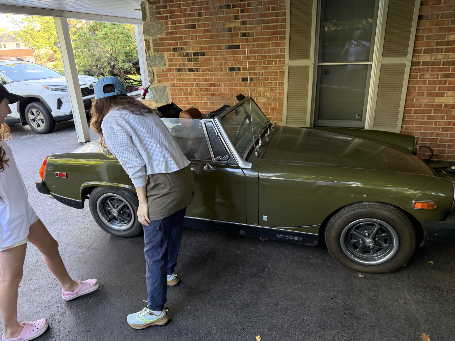
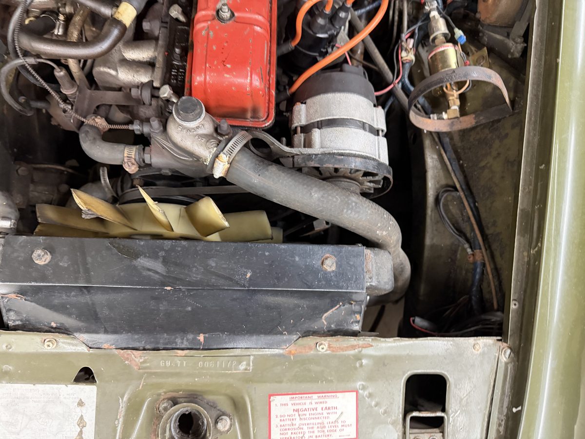
IMG_6341 and IMG_6853 supplement exterior/front-platform and bay context. Those photographs do not establish four mounting axes, body-lip sections, lamp aim or a traced connector circuit. No repeated captures are requested.
Body and mounting relationships
The new hollow nacelles replace the solid ellipsoids. Their 1.2 mm radial offset, front lip and 114 mm radius panel notches are construction geometry, not measured wing sections or a cutting template. A sampled native nose/upper return retains the old central profile and intake datums, with circular corner-round and triangulated-return approximations. Nacelle/lip-to-nose edge coincidence does not establish welds, body ownership or fitted panel alignment.
Four shared body/lip/gasket/bowl bores, three bowl/retaining-ring passages and two bowl/seat trimmer passages expose the mounting roles. Three unassigned rear blade cues connect the complete-unit envelope toward the opaque adaptor; the trimmer heads have estimated retaining-ring access openings. These are construction boundaries, not a fitted connector or clip specification. Rear wiring ports and separate local adaptor/grommet/three lead tails remain unassigned boundaries: no pinout, polarity, earth or remote harness connection is inferred. Gaskets, spring boundaries, clips, screws and retainers are unloaded. Their shapes do not prove engagement, seating, compression, aim range or a functioning electrical/optical system.
The source-contact sample reports intersections with retained wheelhouse/closed-bonnet references. Separate pair volumes remain in the geometry metadata; these are reconstruction discrepancies, not findings of actual-car interference. The existing bonnet, wheelhouse, engine and cooling sources remain unchanged. Other indicator/marker/rear-lamp approximations remain outside this batch.
The shared front-body export now also contains native curved wing shells and inward arch returns. Those replace the browser wing surfaces under retained estimated boundaries; the lamp meshes and their reference axes stay. The wing-to-nacelle transition and mounting flange remain incomplete, and reported source contacts do not prove a fitted seam.
The rear edge of the nose’s upper return now follows the reduced estimated bonnet crown. The front profile/intake, lamp axes, nacelles, wings and landing panel stay. Source contacts are recomputed against the revised bonnet; they remain unregistered geometry comparisons, not fitted panel seams or clearance.
Inspection and workshop limits
Housing inspection translations follow their wing reference; rim, unit and retaining comparisons separate forward to expose boundaries. These are display offsets, not a verified release sequence or extraction route. No fitted aim setting, clip-release access, electrical isolation procedure, loaded seating or verified component replacement/removal path is established.
The coordinated shorter-front construction now supersedes the former forward station map. It revises the bonnet/wings, nose/lamp pose, landing/catch relationship, bumper/support beams and wheelhouse front ends together under a selected nominal length. The front-only allocation remains estimated; fitted dimensions, source contacts, support/clearances and replacement paths remain unresolved.
Front side marker: lens, plinth and rear boundaries
The owner’s IMG_6329 side view shows a pointed amber marker ahead of the front wheel, with a bright rim and separate lamp/reflex zones in one lens. The whole-car model replaces two solid blocks with twenty assembly-role comparisons. The old marker centers and all thirty other headlamp/body mesh records stay unchanged.
Factory PDF215 distinguishes RH BHA4968 / LH BHA4969 assemblies, handed amber lenses, lens gasket37H4753, holder244700, bulbGLB989, body gasket37H4752, Midget plinths AHA9338/9339 and plinth seal AHA9485. The smooth model distinguishes those roles without assigning fitted parts or wiring.
Moss’s L824 comparison, PDF60, gives140×57×22mm assembly bounds and front/rear photographs. Vintage Supplies’ handed pair gives approximately140×55mm and50mm stud centers. The2mm discrepancy remains unresolved; neither set measures this car. The model uses the Moss major boundary and the separate supplier stud-spacing comparison. Moss’s MGB plinths AHH9964/9965 remain distinct from the factory Midget references.
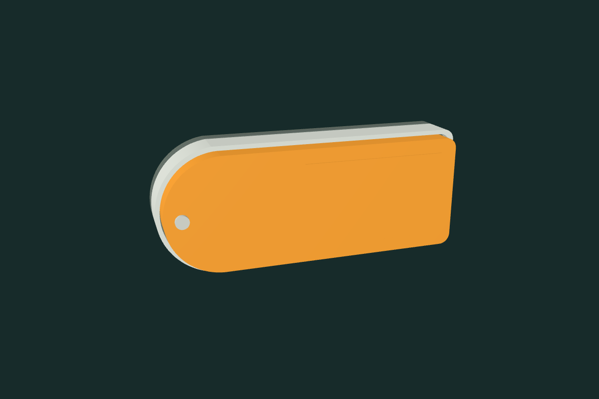
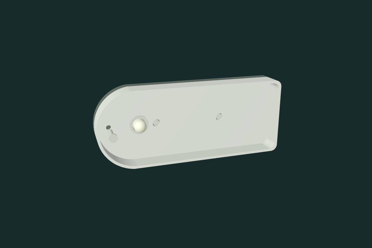
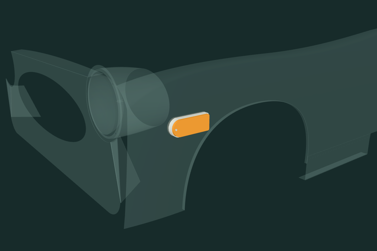
Every internal section, wall thickness, outline, plinth, screw size and sealing relationship is estimated. Point-forward orientation follows the visible left marker; the opposite side is an unverified mirrored construction. Plinths, fixings and local tails extend outside the catalog lamp boundary. The wing receives no new holes. The smooth stud sets and unassigned local tails do not establish thread engagement, grounding, pinout, loaded sealing, optics, compliance, service access or a replacement procedure. Static checks retain two lens/seating-frame overlaps of about689mm³ each and eight positive contacts between the marker comparisons and the uncut wing skins. Plinth seals account for about5538mm³ per side; plinth, holder and fixing boundaries also contact the wings. Those values are reconstruction conflicts, not measured deformation or fitted interference. The separate front side/flasher comparison is described below; its fitted registration remains unresolved.
North American front side/flasher lamp comparison
The model now includes sixteen separate assembly groups for the paired front side/flasher lamps. They retain every earlier headlamp, marker and body mesh. Their dimensions and drawing positions are estimates: the inspected owner views do not show a fitted lamp mounting map.
Factory PDF 211 lists the USA/Canada BHA5320 side/flasher lamp from GAN6-154101, with lens 37H8759, bulb GLB380 and rear grommet 27H6679. The preceding indicator-only BHA5318 / GLB382 branch remains distinct. A shared lens reference does not identify a complete lamp or its circuit.
BP Northwest’s BHA5320 product photograph supports the curved amber lens, two front screws, rear housing and local tails. Its 1976–79 label, Lucas 56707/56705 references and reproduction 164-156 cross-reference remain separate from the factory change point. Moss PDF 89, printed page 71, distinguishes Lucas 164-155 from reproduction 164-156. Holden’s L930 listing is expressly UK spec, so it does not establish the North American holder or circuit. These listings establish comparison roles, not a parts recommendation.
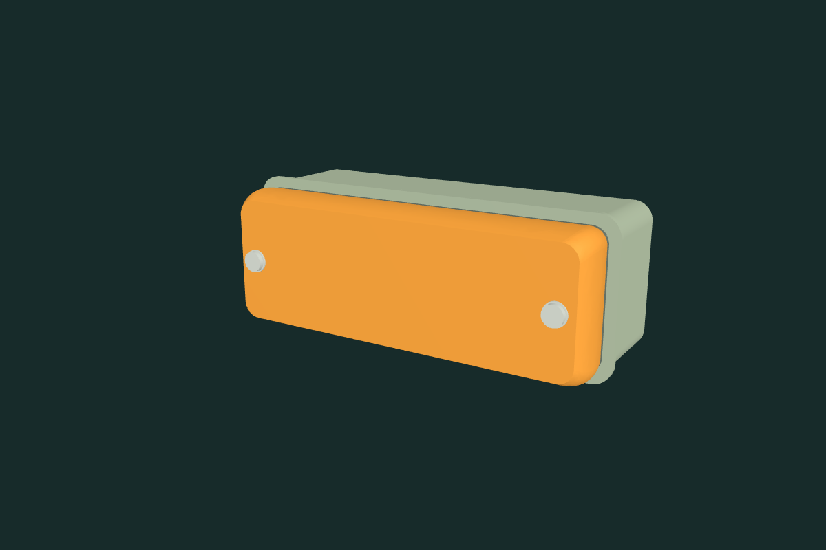
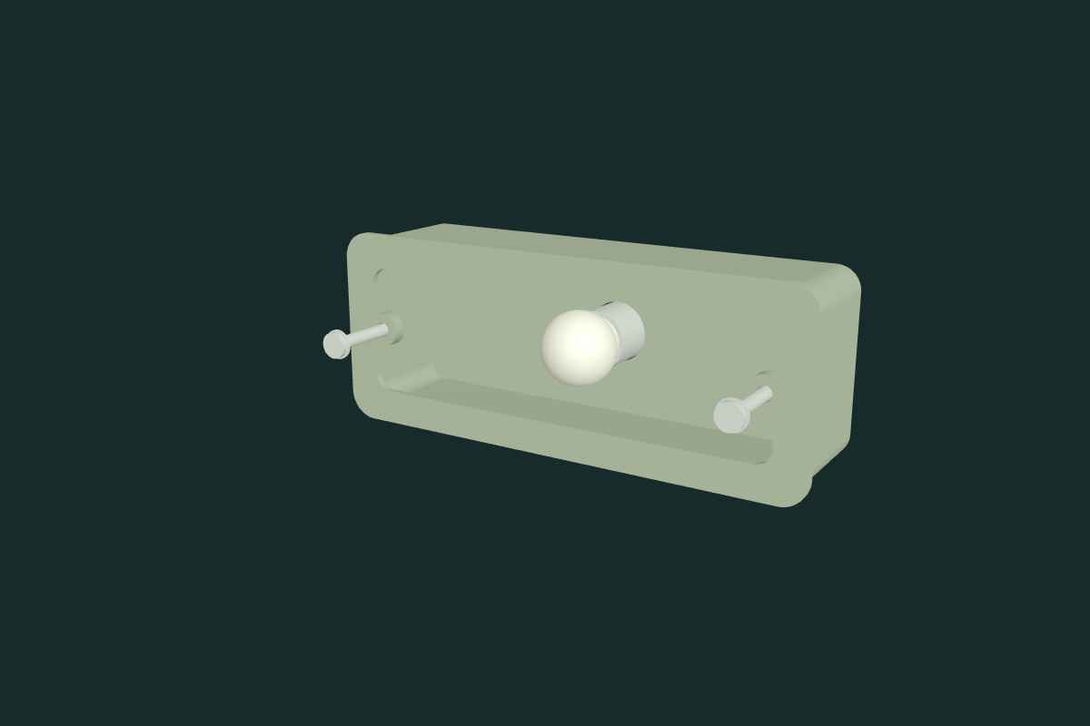
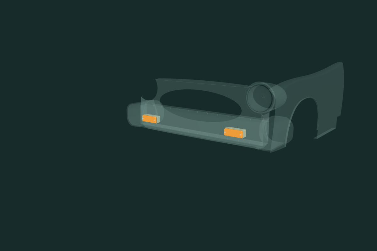
The lens is estimated at 140 × 50 × 18 mm; the bowl, flange, rear port, 122 mm lens-screw spacing, seals, bulb and holder are also construction estimates. No supplier dimensions are adopted as owner measurements. The rear grommet is open and unloaded; three short wire tails have no assigned polarity, ground or destination. The GLB380 role has no modeled filaments or selected wattage. Mirroring is unverified. No bumper or nose opening was cut, and no surrounding part moved to manufacture fit. Static checks found no positive overlap among the new lamp parts, but retain seven contacts with the bumper moulding or armature. Bowl/moulding intersections are about 6043 mm³ per side; bulb/moulding intersections are about 2067 mm³ per side. These include material where fitted receiving openings are unverified. The holder and local tails also have disclosed contacts. Exact values remain in the validation record; they do not prove fitted interference, sealing, service access or removal order. No working circuit, regulatory approval or verified replacement procedure is claimed.