A skin over
a formed framework.
A thin native skin, folded side channels and rear/front formed rails replace the old double surfaces and round-tube braces. The rear rail has access apertures and hollow hinge lands with shared fixing holes. A separate bored stay tab and pin follow the revised surface at the retained upper X/Z station.
Inspect the structure
Reduced transverse crown
The former bonnet rose about 71.967 mm from each side edge to the center at any given longitudinal station. Existing owner IMG_6329/6341 and open-bonnet context support a gentler camber qualitatively; they do not provide a calibrated cross section. The new common surface uses an estimated 21.167 mm center rise, reducing the coarse center by 50.8 mm. These are construction values, not owner measurements or factory crown specifications.
The wing-edge curves, width, front/rear stations and longitudinal profile stay. The thin skin, formed channels/rails, hollow hinge lands, fixing heights and stay attachment are regenerated from the same surface. Only the carried hinge brackets change; body brackets, link eyes and link lengths stay at their earlier unmeasured references. The nose’s rear upper-return curve now meets the revised front profile, while the front intake and lamp stations stay.
The browser’s carried lock/safety mounting, buffer and parked-stay comparisons follow the revised height function. This coordinates the construction without proving fitted latch engagement, unloaded seals, support length or linkage motion. The original single-axis opening remains an illustration, and the static intermediate links and parked support span still hide while it opens.
The modeled bonnet rear center is now about 18.9 mm above the scuttle plane, versus 69.7 mm before. That is a source-coordinate difference, not an actual measured gap. The updated cabin construction coordinates the fascia/column heights as estimates; fitted cabin heights, screen/body registration, true bonnet section and surrounding joints remain unresolved. Factory bonnet/hinge/stay branches establish architecture and remain distinct from this car’s unselected fitted variants.
The current static roof sample uses the relocated intake housing/inlet/cap, revised heater pose and retained rocker cover. No positive contacts appear in that limited sample. Headlamp-nacelle and wing-edge source contacts remain in the front-body metadata. Neither result establishes whole-car clearance, hot movement, loaded closure or an extraction route.
Keep the evidence distinct
Owner observation
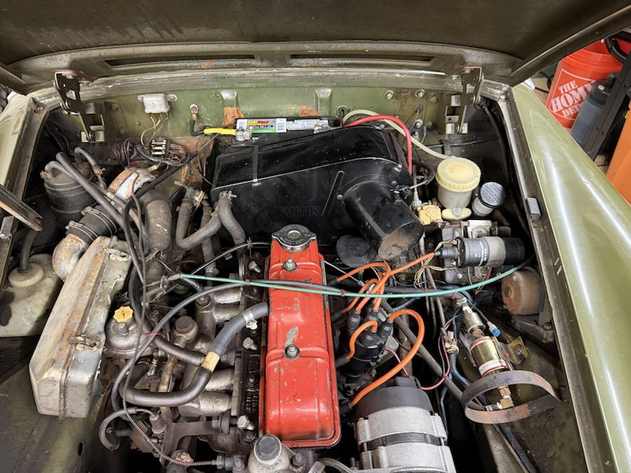
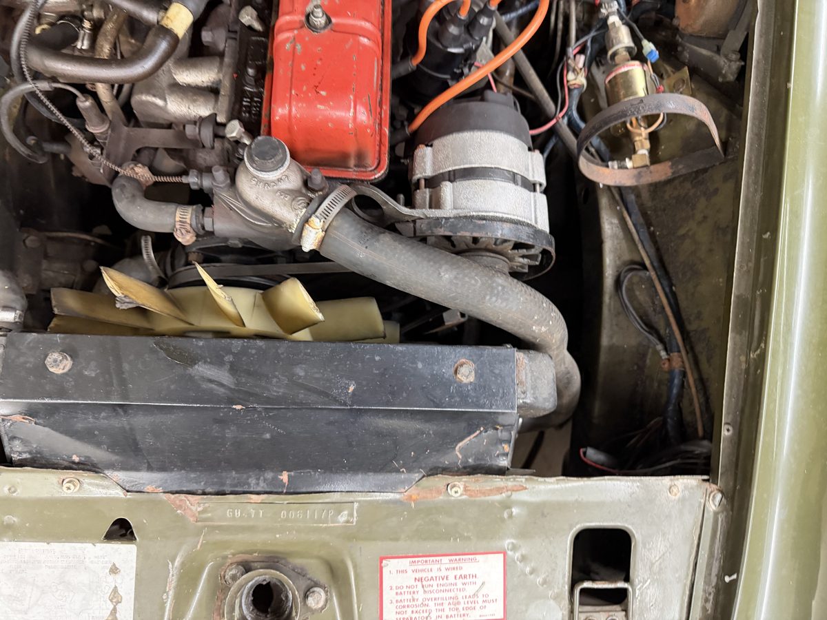
IMG_6856 shows the rear slotted pressed rail and both bulkhead hinge regions. IMG_6853 and IMG_6855 provide front closure/bay context. They do not calibrate skin gauge, cross sections, mounting centers, stay travel or a common bonnet/engine/body frame.
Supplier comparison
The CZJ380 supplier photographs show four rear access openings, perimeter/front reinforcement and an open middle region. They support the framework architecture and removal of the unsupported middle tube. This modern panel is not identified as the fitted bonnet; no exact outline or aperture map is copied as a measured part.
Factory PDF p. 247 separates North America/Sweden CZJ104/105 hinges from other-market 14A4684 and records the CZJ380/CZJ704 bonnet change at GAN6-183740. P. 248 separates the market-specific support and closure roles. Fitted identities and the actual NA linkage remain unresolved.
Declared construction changes
| Relationship | Change and limit |
|---|---|
| Skin | The side-edge/longitudinal curves and X/Z outline stay; the transverse crown is now smaller as an explicit unmeasured construction choice. The old second surface uniformly15.24 mm below the top is removed; a closed1 mm projected-Y skin replaces it. This is an estimated display section, not measured material gauge or a uniform normal offset. |
| Inner framework | Estimated1.2 mm projected-Y side channels and formed rear/front rails replace round tubes. The old15.24 mm lower mounting datum is retained only on these local reinforcements. Rear apertures, folds, hollow lands and captive-boss envelopes are reference shapes, not stamping or repair templates. |
| Bonnet-side hinge fixings | Four screw/washer envelopes share estimated holes with the existing carried hinge leaves and new rail lands. The supplier1/4 UNF ×5/8 screw provides a6.35 ×15.875 mm comparison, not fitted HZS405 identity, thread engagement, head standard or tightening. Body-side leaf/bulkhead attachment remains unresolved. |
| Upper stay attachment | The right-side upper X/Z station stays; its height follows the revised surface. A native formed tab, open pin eye and separate pin replace the upper cue. Support identity, side/anchor fit, locking, stroke, gas assistance and load capacity are unverified. No operating extension is fabricated between the moving anchors. |
Opening is still illustrative
Every carried native part follows the retained single display pivot at body[0,1.04,.13] and maximum angle0.82 radians. The skin and frame move together; screws and the upper stay attachment follow the same display transform. This does not reconstruct the actual NA multi-link hinge or certify a sweep. The parked body-side support span still hides when opening, while its anchors remain separate references.
Carried lock/safety attachments and buffer heights now follow the revised surface. Fixed body catch/cable/anchor and bay frames stay; the parked support drawing follows the new upper endpoint only in the closed display. The opening control does not release the catches, lock the stay or establish a safe support state. General separation and the opening view are inspection aids, not a verified removal or replacement sequence.
Limited closed-pose comparison
The new source samples rocker-cover and air-cleaner housing references in the retained engine/body transform and reports 0 positive contacts. This limited static result does not establish fitted bonnet/engine registration, equipment clearance, hinge travel or a removal path. The full bay and operating sweep remain unverified.
Native exports and validation
Eight source groups contain fifteen valid STEP solids. Checks cover connected rails/lands, open hinge/stay bores and STEP round-trip. Viewer checks cover metric placement/picking, skin section, access slots, shared hinge holes, stay eye/pin, carried opening/separation/reset and parked-support hiding. These validate the reference construction and declared display transform, not fitted dimensions or support strength.
The coordinated shorter-front construction now supersedes the former forward station map. It revises the bonnet/wings, nose/lamp pose, landing/catch relationship, bumper/support beams and wheelhouse front ends together under a selected nominal length. The front-only allocation remains estimated; fitted dimensions, source contacts, support/clearances and replacement paths remain unresolved.