What carries
the bonnet.
Separate body leaves and pins, bonnet-carried hinge arms, main lock and independent safety catch now explain the bonnet’s attachment boundaries. Support-anchor, parked-stay, buffer and release-cable references complete the comparison chain toward the bulkhead and front platform.
The bonnet now rotates and translates with the carrier of the estimated four-bar hinges. Both links remain visible, keep their lengths and meet their pins throughout opening. The approximately 47-degree display cap is retained as an illustrative choice; it is not a fitted opening stop or a clearance result. The lock and safety catch are not animated to release before opening.
Separate the main lock from the safety catch
Sixteen native comparison parts now replace the coarse main pin/spring, cup/catch, safety hook/bracket and release-cable shapes. The pin has a pointed end and separate retention shoulder, thimble and unloaded coil; the open cup and keyhole catch are separate. The safety hook has its own pivot and unloaded coil. The release reference has a hollow sheath, separate pull/stem, mounting plate and open ferrule.
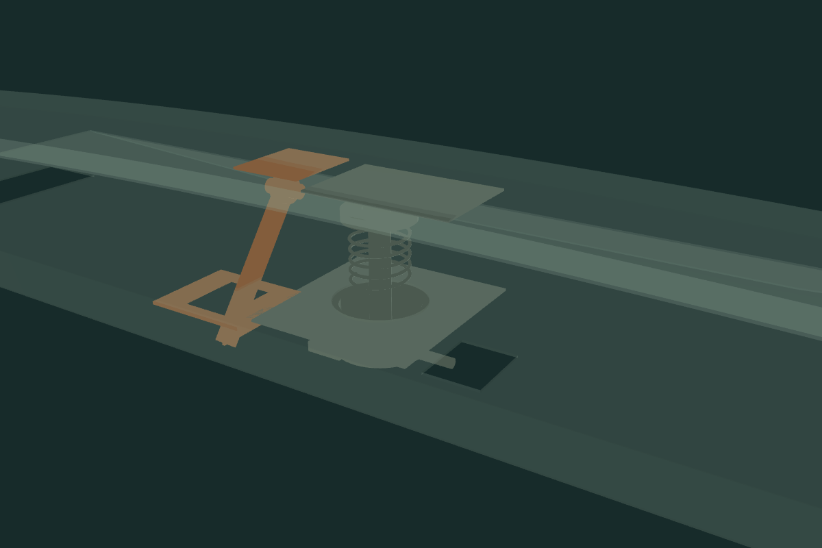
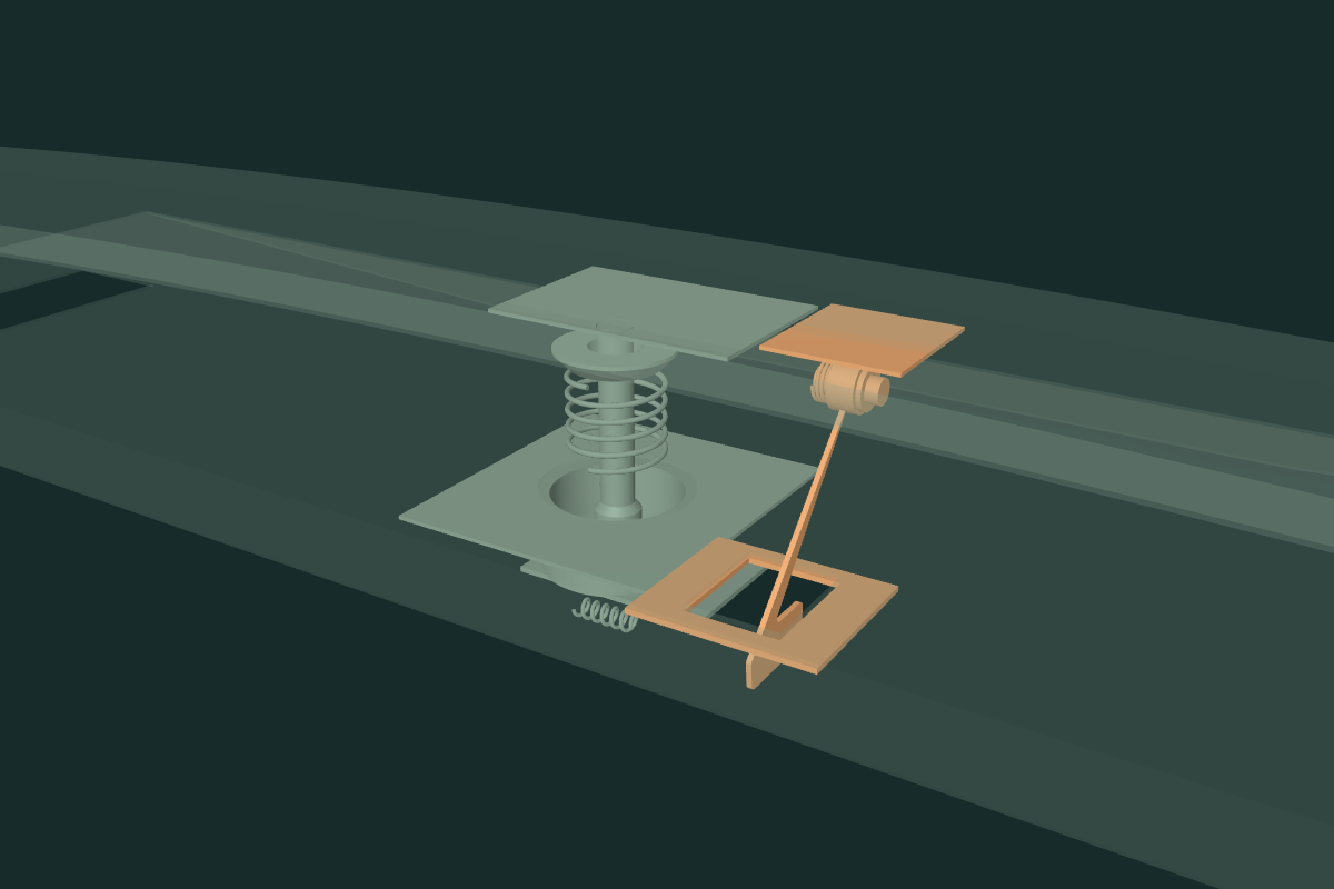
The old browser safety pair reflected to X = −84.67 mm while the native platform slot was at +84.67 mm. The new pair shares that existing slot. This corrects a source-coordinate inconsistency; it does not identify the fitted catch side or verify the slot, hole map or hook engagement. No independent bonnet or body receiver is cut.
Owner IMG_6789 shows the installed pin/spring context and IMG_6853 the front-panel receiver area. Factory plate 248 separates the pin, thimble, pin spring, locating cup, catch/return spring and release cable. Plate 247 distinguishes the safety hook/bracket. Every profile, spring wire/turn count, bore, plate gauge and station remains an estimate. Cable routing, spring-end attachments and hidden receivers remain untraced.
Pin and safety-hook groups follow the existing illustrative bonnet carrier; cup, strike bracket and cable stay with the body. No catch release, spring compression, cable tension or safe open support is simulated. Source contacts remain at the bonnet frame, landing panel and wheelhouse, plus five internal comparison pairs. They do not establish fitted engagement, preload, clearance or a verified removal procedure.
Owner-visible multi-link hinges
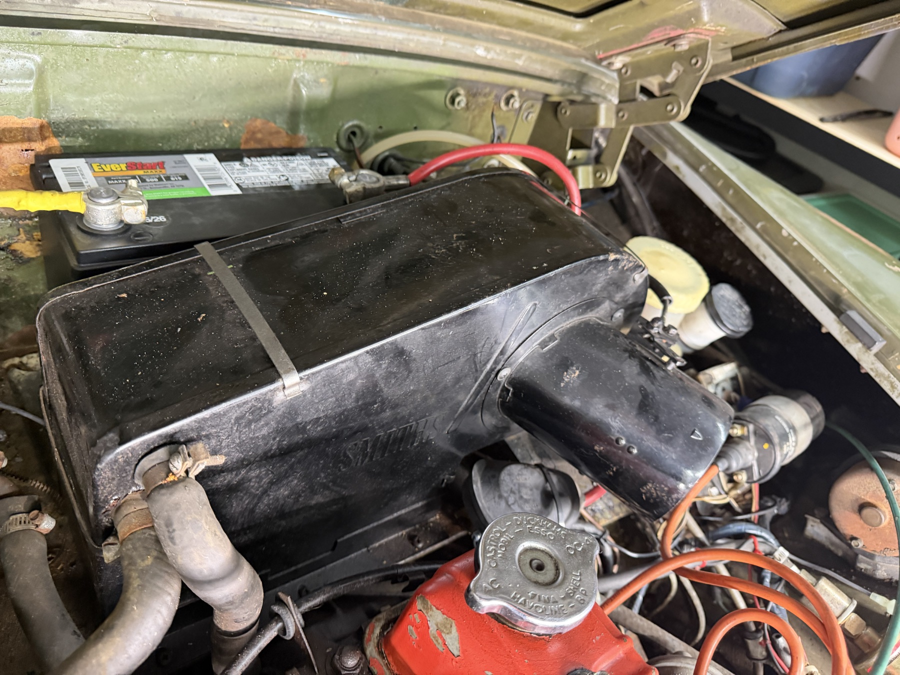
IMG_6892 clearly shows separate body and bonnet brackets, unequal links and multiple transverse pivots beside the battery. This replaces the previous one-pin/simple-arm sketch with separate native bracket, long-link and short-link comparisons on both sides. Existing bonnet-side screw axes stay fixed; link lengths, pin centers, sections, body fixing holes and closed pose are all estimates. Opposite-side details remain a handed comparison, not a fitted survey.
The unchanged closed-reference pivots now define a continuous four-bar solution. Body brackets stay fixed; separate long and short links rotate around their body pins, and the bonnet, carried brackets, lock pin and upper support anchor share the solved carrier transform. General separation adds inspection offsets and is not a connected operating state. No fitted sweep, limit stop, loaded bearing, tool access, safe support or removal path is established.
A connected reference opening
Use Open bonnet in the whole-car viewer. The panel now rises and shifts with the moving hinge carrier instead of rotating about a single fixed point. The unchanged estimated links stay attached. This improves attachment rehearsal, but does not establish real-car travel, collision clearance, catch release or a safely locked stay.
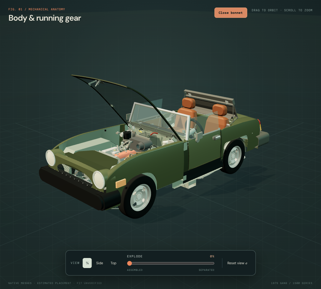
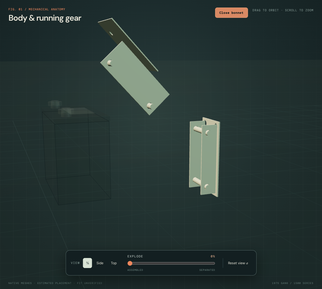
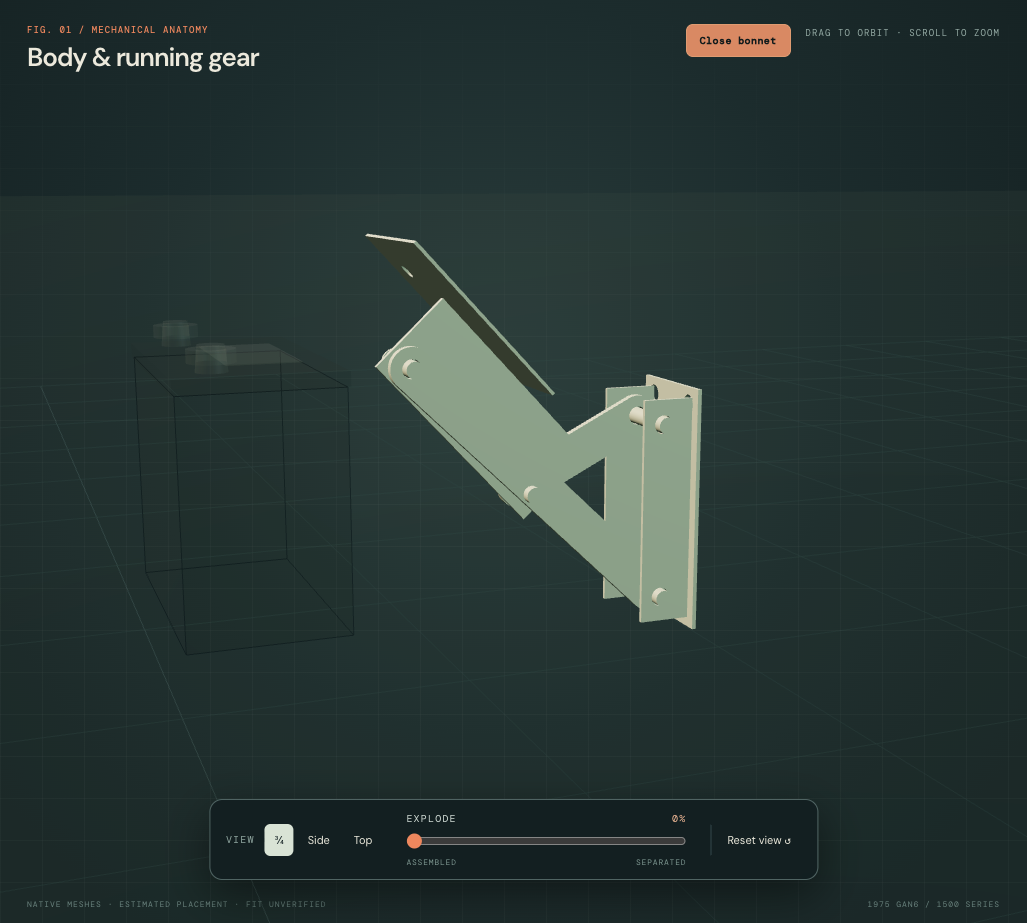
The mathematical check samples 1,001 positions per hinge and preserves all four pivot relationships. Browser checks verify the shared bonnet and hardware transforms through opening and closing. These checks establish internal consistency of an estimated mechanism; they do not validate the mechanism against the actual car. Read the validation and precise evidence gaps ↗
Rear hinge boundaries
Closure and support boundaries
Preserve the market differences
| Factory source | Architecture used | Unresolved fitted detail |
|---|---|---|
| Plate 247 | Handed CZJ104/105 hinges for North America/Sweden, separate from 14A4684 listed for other markets. Independent safety hook/bracket and bonnet/buffer alternatives are listed. | Fitted hinges, leaf profiles, pin axes, mounting bores and actual linkage. The GAN6-183740 bonnet/buffer change does not identify installed parts from model year alone. |
| Plate 248 | USA AHA9800 support differs from not-USA AHA9717. Main pin, spring, cup, catch plate and cable are separate from the safety catch. | Actual support type, side, dimensions, locking mechanism, spring behavior, cable destination and fitted identities. |
Existing owner evidence
IMG_6856 was re-viewed for both rear bulkhead hinge regions and the bonnet underside. IMG_6853 shows the front latch region; IMG_6855 supplies wider bay and side-buffer context. These existing views support component context, not calibrated hinge centers, sections or a complete release-cable trace. No new captures are requested by this study.
What the support display means
The body and bonnet support anchors remain visible when opening. The parked support span is shown only near the closed pose and hides as opening begins. No arbitrary extension is drawn to bridge the moving anchors. This does not imply a gas strut, available telescopic travel, a locked stay or a safely supported open bonnet.
Reference interfaces and their limits
The main pin shares the estimated platform aperture axis; the safety hook has a separate assumed slot and bracket alongside it. That added platform slot is a construction choice, not an observed fitted aperture. Cup, catch, pin and hook shapes do not establish engagement, spring force, clearances or a release sequence.
The cable comparison follows an estimated route from an assumed LHD footwell handle region toward the main catch. Bulkhead crossing, sheath size, clips, end fittings and actual routing remain unresolved. Buffer tops approach the estimated closed underside; compression and real contact are not simulated. All dimensions, gauge, holes and poses are estimates. The native bonnet skin/framework study now supplies formed rails, bonnet-side fixing/land relationships and a bored upper-stay tab/pin. Native closed-pose bracket/link comparisons now replace the browser hinge sketch. Lock/cable comparisons now load from the native closure source above. Buffers and parked-support references retain their previous representation; fitted linkage motion and closure remain unresolved.
Opening and general separation expose reference boundaries. Body-side leaves, closure references and buffers stay fixed; carried parts use the bonnet’s display offsets. Solving the estimated linkage does not prove which fixings to release, actual-car travel, safe support, tool access or a replacement/removal path. Fitted assembly identification and applicable workshop procedures remain unresolved.
Smaller-crown construction update
The revised bonnet crown now changes the carried leaf/fixing and stay heights, plus the lock/safety mounting and buffer references. Hinge body pivots and link eyes stay; the carried bracket changes height to follow the frame. These are coordinated drawing relationships, not measured fitted hinge kinematics, supported operation, catch engagement or a verified removal procedure. The parked support still hides while opening.