FACTORY NOMINALS / UNMEASURED FITTED PROFILES
A rim inside a hollow tyre.
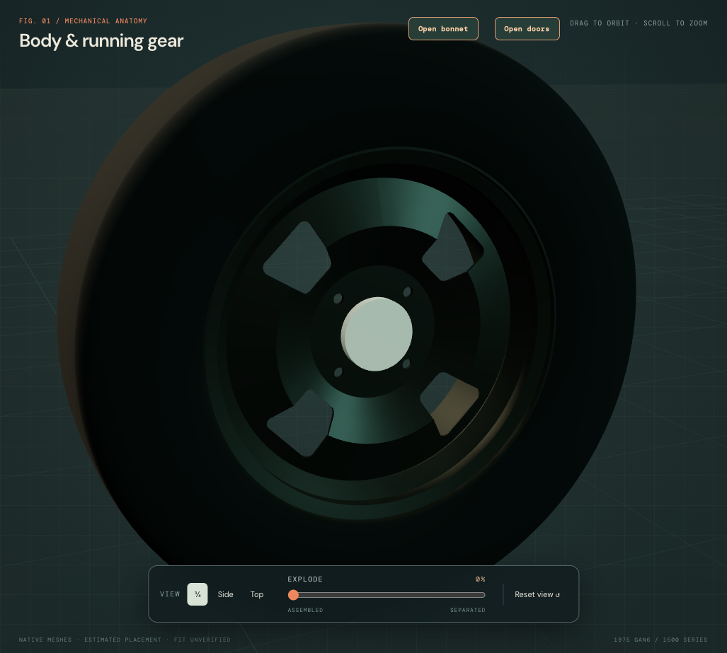
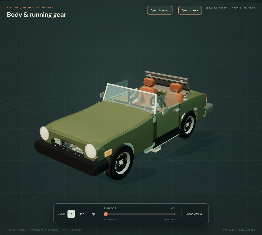
The four road wheels now use handed CAD prototypes with a drop-center rim, formed four-spoke/eight-vent center, hollow tyre, center cap and separate bright outer trim. They replace the thick rim barrel, separate spoke bars and wide tyre-ring/sidewall-torus primitives.
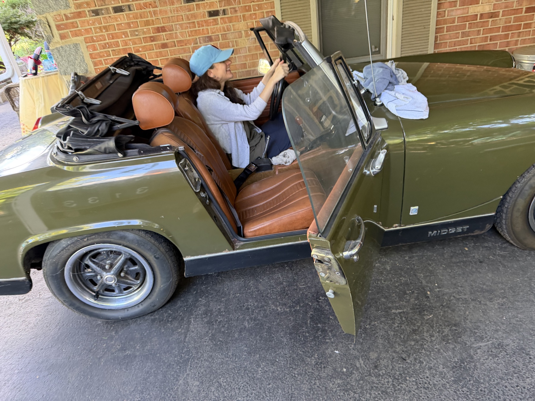
The factory manual lists pressed-spoke 4½ JSL × 13 wheels and 145 SR-13 tyres. The owner photographs show Rostyle-style pressed wheels and bright rim trim, but do not establish their markings, width, offset, tyre size or present condition. The new profiles are nominal comparisons and construction estimates.
Four formed spokes, eight paired vents
The former simple dished center and four large holes are replaced by a connected formed-steel reference with four raised radial spokes and two rounded peripheral openings per recessed quadrant. The vent pairs straddle the stud directions; spokes lie between them. The owner details in IMG_6329 and IMG_6341 support that architecture and dark-center/bright-trim appearance.
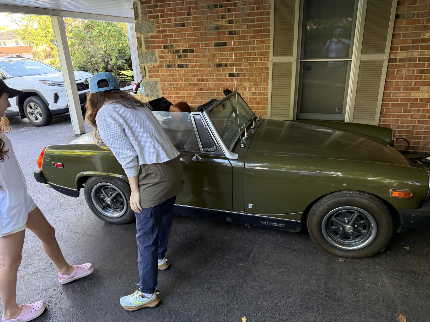
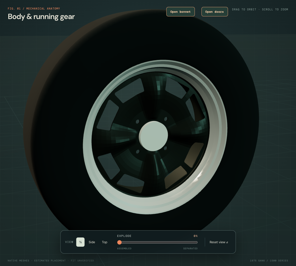
Factory p301 separates AHA8892 and AHA9881 Rostyle alternatives, AHA8785 wheel nuts and AHA8950 center-trim roles. The later supplier wheel photograph supplies an additional pressing comparison. Neither identifies this car’s wheel markings or dimensions; the supplier’s silver finish is not imposed on the owner’s dark centers.
Held datums and estimated sections
The tyre and cap meshes are identical to the previous source. The nominal bead dimensions, outer rim profile, center bore, four stud axes and four instanced wheel positions remain. Local flat lands retain the old X=20–25 mm source planes at the stud positions; these are construction sectors, not fitted nut-seat dimensions or taper. The formed spoke depth, eight vent profiles and projected sheet sections are estimates. The new trim profile and 0.6 mm projected-X section are also estimates; clips and fitted seating are unmodeled.
What can be inspected
Select the steel center, tyre, cap and trim as distinct geometry. The vents now expose the surrounding hub/brake references instead of a solid painted dish. Separate trim geometry does not identify a safe clip-release method, and the wheel separation remains illustrative. Valve/tube configuration, nut seating, loaded fit, strength and actual replacement/removal paths remain unverified.
Native checks cover all eight positive solids, the paired vent and adjacent-material witnesses, stud/center bores, flat-land reference planes, retained outer rim material and selected hub/brake source contacts. The viewer checks all four metric placements and 32 vent rays. These are source-model checks, not fitted or loaded clearance measurements. The existing front rotor-screw discrepancy remains explicit.
Keep nominal and estimated dimensions separate
| Feature | Reference and limits |
|---|---|
| Bead-seat width | 4½ inches = 114.3 mm, from the factory pressed-wheel designation. This is between bead seats, not total outside rim width. The wire-wheel 4J × 13 alternative is separate. |
| Bead-seat diameter | 13 inches = 330.2 mm. Outside flange diameter is larger; its 356 mm drawing value remains estimated. |
| Tyre section | The 145 designation supplies a nominal 145 mm reference envelope. It is not a measured section width on this car, and actual inflated dimensions depend on the fitted tyre and rim. |
| Tyre radius | The inherited 283.6333 mm drawing radius stays. It is unmeasured. No numeric aspect ratio, rolling radius, loaded deflection or ride height is inferred from the designation. |
| Rim and center construction | Drop-center contour, flange lips, 2.5 mm radial gauge, dished pressing, four vent shapes, weld boundary and cap are estimated. The 134.3 mm outside rim width includes estimated flange extensions. |
| Mounting relationship | Existing steel-wheel track and axle centers, 20–25 mm mounting-plate interval, center bore and catalog PCD remain. The fixing-hole map changes from the old browser 0° clock to the existing hub references’ 45° clock. These drawing datums do not establish the fitted wheel offset or hardware engagement. |
What changed in the model
The old tyre primitives spanned about 199.8 mm axially, despite a 145 reference designation. The old rim barrel alone was about 162.6 mm wide. The revised shapes distinguish bead-seat dimensions from outer flange dimensions and provide an internal tyre cavity rather than a full annular rubber mass. All four corners keep their existing centers and separation offsets. Body skins, suspension, brakes and hubs have not been resized to make the wheels fit.
Inspect the service boundaries
Select the wheel to see the whole assembly, or click its source tyre, steel wheel, cap or bright trim and isolate that component. The open bead region and hollow cavity distinguish the rubber, wheel well and center pressing. Nominal seat contact in the drawing does not validate bead compression, inflation, strength, tyre mounting or operation.
General separation remains an inspection convention. It does not establish a jacking/support method, safe release order, nut torque, loaded or steered clearance, brake access or verified wheel/tyre replacement path. The separate hub and brake studies retain their own unregistered mounting references.
The current front rotor-screw envelopes extend 4 mm beyond the estimated wheel mounting plane and intersect the wheel reference. Their actual length, engagement and installed stack remain unknown. This is a source-model discrepancy, not measured contact on the car; the screw envelopes have not been shortened to erase it.
Body-width evidence
The checked factory general-specification table gives a pressed-spoke overall width of 4 ft 5⅝ in (1362.075 mm by inch conversion; printed as 1.36 m). The Moss GAN6 comparison lists 4 ft 6⅞ in (1393.825 mm), while the earlier handbook transcription in this project says 1.39 m. The edition/configuration and measurement-boundary differences remain unresolved. Overall width also does not locate the steel body-panel stations. These values are retained as distinct evidence, not used to scale every body or mechanical part.
Sources and native prototypes
Factory AKM4071/B wheel and tyre specification, p13 · General dimensions, p14 · Moss GAN6 comparison.