Under the front,
from six photographs.
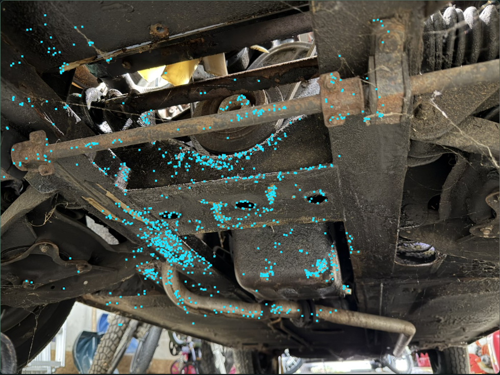
Existing IMG_6914–6919 now connect in one sparse photographic fragment. Orbit the observations or choose an original view to check their projections against the unchanged photo. The source views include the front crossmember, rails, sump, pulley, pipe and suspension surroundings, along with the jack and background.
No physical scale, verified body datum, ground plane or fitted engine transform is assigned. The front end is supported on a jack in these photos; suspension and wheel positions are not a verified road-loaded state. The upper-bay reconstruction stays separate. Neither a camera fit nor missing dots proves clearance or a replacement path.
Loading the photographic reference…
Drag to orbit; scroll or pinch to zoom. Showing a source photo limits the markers to features observed in that image. Orbiting returns to the complete supported point set. The points are not closed surfaces or automatically identified car parts.
Frame and engine references in the same view
Turn on Current frame and Current pulley / sump to compare the existing native geometry with a recovered photo camera. The six meshes retain their exact whole-car relationship. They receive one conditional display transform; no part is independently fitted or moved to improve the comparison.
The two outer aperture-region proxies set the row direction and span. The interpreted aperture surface normal supplies the other display direction, oriented toward the hub proxy. Mapping the current native row onto those features assumes its span and lower-face interpretation for display. It does not recover physical body axes, gravity or an actual engine/body transform. You cannot read fitted millimetre offsets from this overlay.
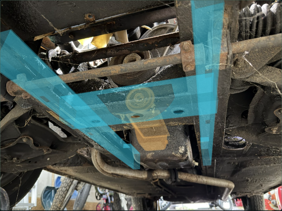
Four interpreted image features now connect the frame aperture row and visible hub region. The two-view fit projects the three aperture proxies into IMG_6916 within about 0.3–4.0 source pixels. Rounded hub-center proxies in IMG_6916/6917 differ from their predicted projections by about 4.3/1.6 pixels. Those additional views did not enter the fit; the checks share the same photographic reconstruction and are not independent measurements.
The hub-proxy distance from the outer-aperture midpoint is about 0.720 of the outer proxy span. A separate per-image camera solve gives about 0.717 using the same interpreted picks. It shares the photographs and is a camera-hypothesis check, not an independent survey. The current modeled nut/collar reference gives about 0.366 of its row span. That ratio survives display rotation and scale, but it still compares interpreted image regions with an unverified native axial reference. It exposes a substantial relationship to reconcile, not a measured engine displacement. The aperture shadows are not mechanical hole axes, the hub opening is partly occluded, and its axial plane/identity are not established.
The face normal is also not a known body or ground normal. Different face-tilt assumptions change the apparent height and fore/aft components. The scalar ratio does not choose which engine pose, frame dimension, hole station or component identity should change. Keep the native frame, engine, gearbox and exhaust unaltered until a defensible common datum chain resolves that ambiguity.

What this resolves
The earlier test tried to match these views to the existing upper-bay points and did not recover an accepted camera. This solve instead uses the overlap among the six underside photographs themselves. All six register together, with 2,464 raw points and 2,096 passing the display filter. That establishes a new relative observation frame for further datum work; it does not correct the whole-car CAD yet.
Why the exhaust finding still needs a common frame
The current CAD cross-box is only about 8.47 mm above its estimated unloaded tyre-bottom plane, while the original 1975 bulletin lists 82.55 mm ground clearance. These are different evidence classes. The rear silencers and full underfloor route are not surveyed in this front fragment, and the photographed jack support prevents treating its wheel positions as the model's nominal ground state. Raising one silencer to match the published number would not establish the actual support chain.
Next, reconcile the interpreted proxies with physical feature identities, a measured scale and independent body datums. Keep interpreted hole shadows separate from physical hole axes. The earlier two-hole camera estimate and provisional native dimensions are not accepted physical registration.
The first surface-patch comparison now supports a lower-face aperture interpretation in the native front member, superseding its former forward-web openings. The patch angles do not recover a precise factory plane or engine/body datum. Physical scale and common registration remain open.
Camera assumptions and evidence limits
The shared solve uses a centered SIMPLE_RADIAL camera, with focal length and radial distortion refined. A 24 mm-equivalent starting prior is supported by previously read original metadata for IMG_6915 and IMG_6919; the other four inherit a camera-family assumption, not independently recovered EXIF. Low reprojection error is a fit to these images, not millimetre accuracy.
Displayed points need observations in at least three images, a maximum triangulation angle of at least five degrees and mean error no greater than two analysis pixels. Tracks can include cobwebs, the jack or garage surfaces. They are not a complete car surface, a collision model, a surveyed floor or an operating clearance envelope.
A separate per-image camera solve also registers all six views. Of 501 paired tracks observed in at least two photos, 495 agree within the selected 3% reference-span threshold after a similarity fit. Across all 501 pairs, median difference is about 0.50% of the arbitrary reference span, the 95th percentile about 1.39%, and the maximum about 8.41%. The span is a reconstruction statistic, not a measured car dimension. Shared photos and different feature/camera assumptions make this a sensitivity check, not an independent survey.
Processing uses PyCOLMAP. Downloadable cameras, tracks and validation preserve the exact reviewed result. The original photographs, upper-bay solve and existing native CAD stay unchanged.
Pulley size versus the aperture row
The earlier hub-to-row distance comparison could not distinguish engine placement from frame dimensions. A second relationship concerns size: the distance between the two outer aperture proxies divided by an interpreted pulley-rim diameter. That ratio is unchanged by moving or rotating the engine and frame.
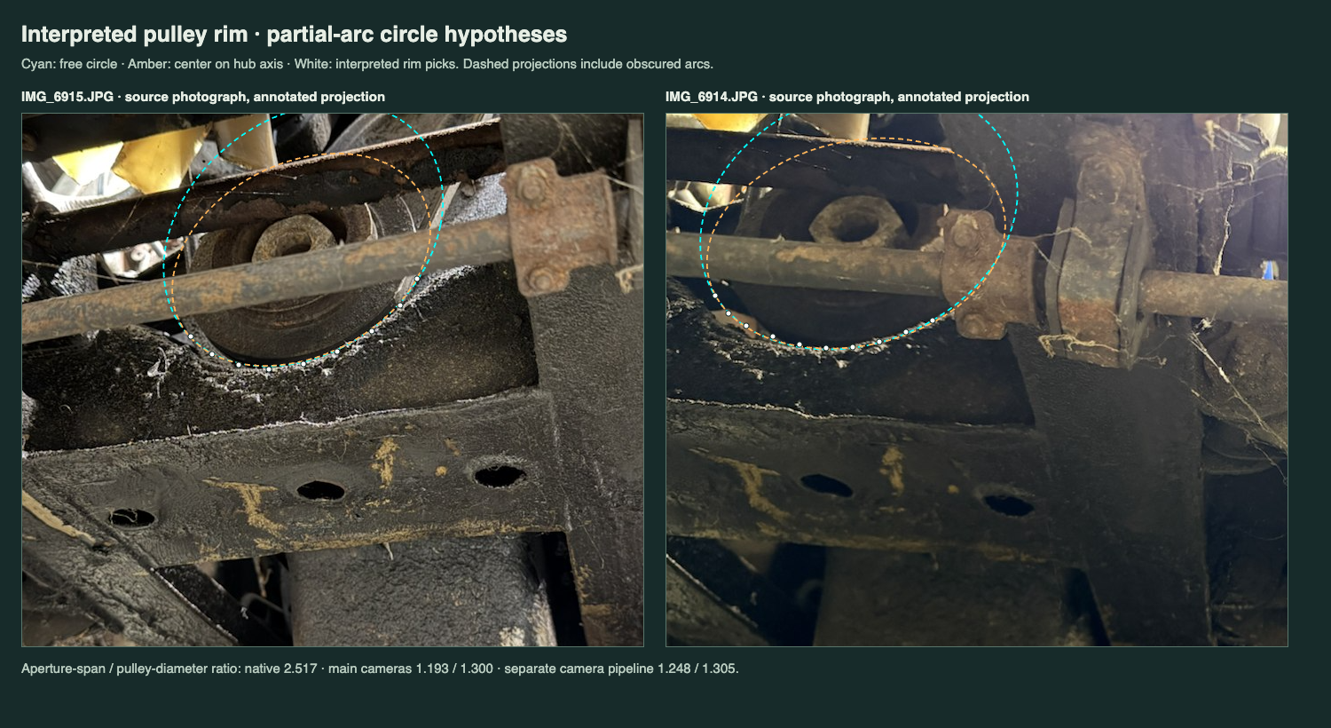
| Reference / hypothesis | Outer-aperture span ÷ pulley diameter |
|---|---|
| Current native frame and pulley | 2.517 |
| Main cameras · free / hub-axis circle | 1.193 / 1.300 |
| Separate camera pipeline · free / hub-axis circle | 1.248 / 1.305 |
Nineteen points on visible lower arcs enter the two-view fits. Their root-mean-square Sampson residuals are about 1.5–2.0 undistorted source pixels across the four two-view hypotheses. The different results expose the dependence on partial arcs, cameras and the unverified hub-axis assumption. A fixed-camera ±2-pixel perturbation exercise gives a 1.055–1.308 5th-to-95th percentile ratio for the free circle; it excludes feature and camera uncertainty and is not a confidence interval. The additional views were inspected after projection; occlusion prevents independent continuous-rim validation.
The TKC1425 supplier listing gives 148 mm outside diameter for its two-belt comparison. Its side photograph distinguishes the large rear and smaller forward rims; it does not identify this car’s pulley or calibrate the picked lip. Equating the photographed circle to 148 mm would imply roughly 177–194 mm aperture-proxy spans in these examples. Those are conditional calculations, not selected actual-car dimensions or a repair width.
The transverse frame construction needs review before an engine-offset correction. Changing only the engine position leaves the native 2.517 size ratio unchanged. Resolve the matching pulley rim, aperture boundaries, rail faces and pickup identities before revising those related dimensions together. Current native geometry and placements stay; no fitted scale, body axis, loaded clearance or replacement path is established.