The fitted filter is
an ACDelco PF53.
IMG_6966 clearly shows PF53 on the blue filter installed on this car. This closes the earlier identification gap and improves the CAD envelope. The filter's mounting thread and seal are hidden in the photo, and the block-side adapter has not been identified. Keep those checks in the project before buying a substitute.
Record PF53 currently installed and adapter unverified as separate facts. Rimmer lists GFE119/GFE150 for the Midget 1500 but explicitly warns that some aftermarket filters use different threads and adapters. A model-year catalog suggestion alone does not prove it will fit the mounting hardware visible on this car. The nominal threads conflict: the photographed PF53 is listed at ¾-16, while the GFE150 Midget 1500 catalog branch has a ⅝-18 opening. A ⅝-18 to ¾-16 adapter stud exists for these cars, but the adapter on this engine has not been inspected.
Closed-end shape: IMG_6966–6967 show a rounded canister end. The CAD now follows that silhouette while retaining the separate straight-shell diameter, rolled seam, total height and mounting-socket datums. Its public 5 mm corner is a photo-led estimate; owner diameter and height readings scale the template's radial and axial extents independently. They do not measure a real corner radius, dome or wall, and the end rounding does not resolve the missing baseplate/gasket seat.
Photo evidence
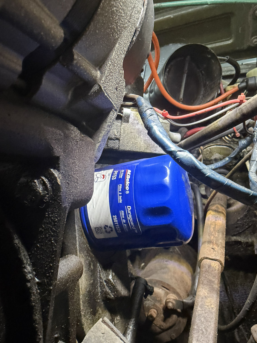
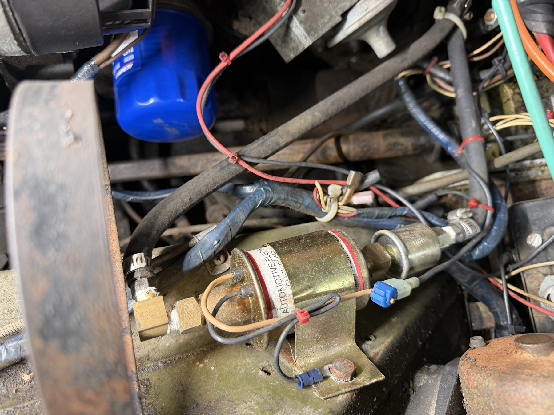
Dimensions and fitment evidence
| Question | Documented value | Limit for this car |
|---|---|---|
| Installed part | ACDelco PF53, read from IMG_6966. | Its condition, date, seal and internal specification cannot be read from the exterior photo. |
| PF53 outside envelope | The JEGS PF53 listing gives 3⅛ in height (79.4 mm) and 3 1⁄32 in outside diameter (77.0 mm). | These are catalog dimensions for PF53, used in the revised CAD; measure this installed canister before using it as a clearance datum. |
| PF53 connection | The same listing gives ¾-16 thread and gasket diameters 70.4 mm outside / 62.2 mm inside. | The fitted adapter's thread, gasket seat and bypass arrangement are not visible. Check them during a planned change before selecting any replacement. |
| Catalog Midget 1500 filter | Rimmer lists GFE119 and cross-references GFE150 for Midget 1500. | Rimmer warns that aftermarket adapters can differ; this is a catalog branch to compare, not proof of interchange with the fitted PF53. |
| Catalog filter thread comparison | British Parts Northwest lists GFE150 for Midget 1500 with a ⅝-inch opening; the MANN W 713/14 specification identifies this comparison branch as ⅝-18 UNF. PF53 is ¾-16. | The nominal threads differ. Determine which adapter stud and filter-head arrangement is actually fitted before ordering or changing filters. |
| Alternative dimension example | WIX lists 51374 for M.G. 1975–80 at ¾-16, about 75.3 mm diameter and 89.6 mm height. | Matching nominal thread is insufficient: compare gasket seat, valve specification and access clearance with the actual adapter before buying. |
Survey the fitted rim and axis separately
Diameter and height do not locate the filter in the engine bay. The public model’s downward axis is a reconstruction choice. A new direct spatial survey can produce a rim circle and axis reference in your named physical frame, without treating the hidden mounting joint as measured.
- During planned access, establish a fixed right-handed frame with perpendicular unit axes. Record its origin, positive directions and the installed or removed configuration. A removed filter’s pose does not establish its installed axis; do not mix readings from configurations.
- Identify one reproducible circular section on the rim. Record at least four distinct 3D points on that same section with individual physical datum notes. The first three must be widely spread; the remaining points check the circle and its plane. Whole-part X/Y/Z sizes and photo pixels cannot supply these coordinates.
- Independently measure that rim-section diameter and the distance from its plane to the closed-end extreme plane normal to the axis. Record the separate measuring method and endpoints. Survey a point on that confirmed extreme plane; it may be off the axis. A point elsewhere on the rounded end does not establish that plane. If the datum cannot be confirmed, leave the record incomplete.
- Use an explicit comparison limit to review circle/plane check residuals and the independent diameter/depth disagreements. The tool does not infer instrument uncertainty or a fitted tolerance, average the points or move readings to force agreement.
Different datums: the chosen rim-section plane is not the gasket sealing plane. Its distance to the closed-end plane is not automatically the inspector’s total canister height. Keep these records separate.
Build and review the reference
Use the project’s CadQuery environment and keep both Python files beside the existing CAD tools. Replace the comparison-limit placeholder with your chosen limit in millimeters; choose a new empty output directory.
python build_filter_rim_survey.py --survey my-filter-rim-survey.json --output-dir owner-filter-axis-survey --comparison-limit-mm YOUR_COMPARISON_LIMIT
The report keeps the original record, all named points, signed plane/radius residuals and independent diameter/depth differences. Failed comparisons produce the report only. A passing comparison exports filter-rim-axis-reference.step with one circular wire and one axis line, with no material solid. The points are in the surveyed frame; placing them in the engine CAD needs separate checked registration to corresponding datums in that exact model.
Compare with a named CAD frame
Use the blank survey-to-CAD registration record and filter reference registration script from the full project CAD directory. This reuses the existing rigid-registration tools; it does not import a new filter solid into the browser.
- Copy the rim survey’s complete source frame and configuration exactly. Survey at least four identifiable fixed datums in that unchanged frame. Give each source point its physical datum and measurement note.
- Record the actual corresponding CAD coordinates in the exact target model, with separate extraction notes and a named target frame. Enter that file’s SHA-256 hash in the record. If the CAD lacks a corresponding datum, leave the registration unresolved rather than substituting a nearby point.
- The first three ordered pairs define the rigid transform. Keep at least one unused check datum 5 mm or more outside both construction-triangle planes. Construction sides must be at least 5 mm and angles 5–175°; these are tool-conditioning limits. Use a separate explicit registration comparison limit.
shasum -a256 target-model.step
python register_filter_rim_survey.py --survey my-filter-rim-survey.json --registration my-survey-to-cad.json --target-model target-model.step --output-dir owner-filter-cad-reference --survey-comparison-limit-mm YOUR_SURVEY_LIMIT --registration-comparison-limit-mm YOUR_REGISTRATION_LIMIT
Choose a new empty output directory. Both comparisons must pass before filter-rim-axis-cad-reference.step is exported. The output remains only a rim circle and axis edge, now in the declared target frame. Open it alongside the exact target model in your CAD application. Failed comparisons write filter-rim-axis-registration-report.json without a STEP. Source and target observations, both original records, the model fingerprint and all registration residuals stay in that report.
A matching hash identifies the target file; it does not verify the manually extracted datums or provisional target geometry. No scale, reflection or least-squares fitting is used, and no engine file, gasket seat, material shape, contact, clearance or removal path is changed or verified.
This tool does not reshape the public filter, identify a PF53 or its adapter, establish the seal face, model the canister interior or prove collision clearance and removal travel. Its 5 mm point separation and 5–175° construction-angle limits are numerical conditioning guards. The 20–200 mm diameter and 5–250 mm axial ranges are tool bounds, not filter specifications.
What the CAD opening establishes
The model now has a central socket so its provisional adapter does not occupy solid canister material. Its 10.2 mm radius and axial depth are display estimates around the modeled sleeve, not PF53 thread dimensions or measured engagement. The rest of the canister is an outside envelope; filter media, valves, inlet holes, wall thickness and the real baseplate are omitted. WIX describes thread engagement at a spin-on baseplate as general construction, not evidence of this PF53 or its fitted adapter.
The hidden gasket seat is still missing
The public model seal-support report checks face contact separately from solid overlap. In this reconstruction, the gasket's head-facing annulus has full modeled contact, but its canister-facing annulus has none. The closest canister distance is 0.5 mm radially; the body face beneath the gasket footprint is 2 mm lower. These are different model quantities, not measured gaps on your car. A zero-overlap check cannot establish that the seal is supported.
The oil-filter assembly study now shows the seal-support record attached to the current native export. A newly built owner model gets its own calculation after supported measurements are applied. Older exports without that record remain unchecked; the viewer does not substitute this public report. Browser size previews and illustrative separation do not recalculate face contact. Even complete modeled support would not certify the fitted seal.
ACDelco's general design illustration shows a plate/canister seam and retained sealing gasket. It is not a PF53-specific cutaway and supplies no dimensions for this car's hidden baseplate. The CAD has not added a guessed seat to make the audit pass.
During a planned change, photograph the removed PF53 base square-on and side-on with a scale. Record the seat or groove's inside/outside diameters, its named metal support face, seat depth and gasket projection. Keep loose gasket thickness separate from installed compression, and survey the baseplate, rim and gasket in one shared datum. Also record the actual head sealing annulus and adapter thread. Neither overall height nor gasket diameters alone establish that hidden stack.
Survey the seat as measured surfaces
Use the blank seat-surface worksheet during planned service. This separate local tool exports two directly surveyed faces: the metal seat floor and the retained gasket's head-facing surface. It does not add guessed material to the public canister, and it does not accept catalog dimensions or photo estimates as direct readings.
- With the filter removed and free of mounting-head load, choose an accessible, named metal reference plane normal to the filter axis. The local origin is its intersection with that axis. +Y points outward toward the mounting head; record an X witness and the corresponding right-handed Z direction.
- Before lifting the gasket during planned access, record the outside and inside edges of its actual head-facing annular surface, and that face's signed projection from the metal reference plane. Positive is outward toward the head; negative means below the reference. These face edges are not automatically the removed loose gasket's widest edges.
- Keep the filter and physical reference fixed while accessing the seat floor. Record that floor's own outside and inside diameters and its depth below the same reference plane. Retain a fixture or witness record tying the before/after readings together; an arbitrary moved-part position is not the old datum.
- Confirm both recorded faces are nominally circular, flat and coaxial. Describe the measuring method, faces, photos and capture states. Curved, stepped or distorted surfaces need a profile survey instead of this two-annulus tool. Do not remove the filter or gasket solely to complete the worksheet.
Set method to direct and configuration to removed-filter-no-head-load. Supply the source and frame notes, and set each geometry/frame confirmation to true only after checking it. Leave unknown readings blank; the tool requires all six named dimensions. From the CAD source directory, in a Python environment with CadQuery:
python build_filter_seat_surface_survey.py --survey owner-filter-seat.json --output-dir owner-filter-seat-surfacesThe STEP contains two open surface faces and no solids. Its evidence JSON preserves your original record, local datum notes and independent readings. Their axial span is not free gasket thickness or installed compression; the removed gasket may retain deformation. Baseplate thickness, groove walls, gasket section and lower face, threads, identity and engine placement remain unknown. The files are separate from engine-builder measurement logs and the web mesh loader.
Supported tool ranges are face outside diameters 20–120 mm, inside diameters 10–110 mm with positive annular width, floor depth 0–20 mm and signed gasket-face projection −20 to +20 mm. The head-facing plane must lie outward of the floor plane. These limits are not PF53 specifications or fitted tolerances. Uninstalled measured faces do not establish seal support under load or a removal path.
Record the exposed adapter
During a planned filter change, select the threaded adapter in the CAD inspector and record its exposed male-thread outside diameter and tip projection from the head face contacted by the filter gasket. Direct readings with a measurement-point note can reshape only the exposed portion in a separate owner STEP and web build. The hidden head-side end and passage remain estimates; no thread form or pitch is inferred from the diameter. The socket follows with separately labeled display clearance, not a measured filter opening. Open the generated owner JSON to inspect the result; the filter-only browser preview retains the public adapter. Do not unscrew the adapter just to measure it.
Understand the axial viewing limit
A direct mounting-plane-to-obstruction reading bounds the study's downward movement using the displayed canister or gasket's furthest extent from the model head sealing plane. Height alone cannot locate a part relative to that plane. The limit also applies to downward explode movement while the filter study is active. The model's sealing plane and downward axis remain provisional; this calculation does not register the filter to the actual car or prove an unscrewing, sideways exit, hand or tool path.
If an older local build has a recorded obstacle but lacks the sealing-plane datum, the study holds axial movement at zero and asks you to rebuild it from the original measurement log. Without a direct obstacle reading, separation remains illustrative.
Plan the next oil service
- Photograph the PF53 label, filter-to-head joint and surrounding distributor, hoses and wiring from several angles. Measure the installed canister's straight-shell diameter, rolled-seam outside diameter and overall height if accessible without moving it. Record the shell and seam separately in the CAD inspector; the seam's axial height and inside profile are still estimates.
- Find the sump drain and dipstick on the physical engine; neither location is established by the photos. Confirm safe vehicle support and a catch-pan path before starting.
- Before ordering, compare a candidate's thread, gasket outside and inside diameters, valve specification and installed clearance with the PF53 and the actual adapter. The ¾-16 PF53 versus ⅝-18 catalog filter difference makes the adapter a required check.
- During the planned change, record the removed filter's thread and gasket, inspect the adapter and seating face, and make sure the old gasket has not stayed on the head. Photograph the removed baseplate square-on with a scale and measure the adapter thread outside diameter and its projection from the head sealing face. Photograph the findings for the project log.
- Follow the oil-service guide and the applicable filter instructions for installation and final level. The nominal sump-plus-filter fill is a starting amount; the dipstick is the final check.
- Resolve the apparent fan damage before running the engine for a leak check. Record the installed replacement number, oil, date, odometer and a dry filter/drain result after safe operation.

Read contact results for the loaded source
The filter study now applies its native contact percentages and face areas only after the canister, gasket, head and adapter source meshes all match their export’s record. Older unbound records and incomplete or mismatched sources remain explicitly unchecked. A size preview withholds the original percentages because it resizes displayed parts; return to the exported size to review that record. During virtual separation, the figures continue to describe the original assembled pose.
The public source still has full modeled support on the head side and none on the canister side. The nearest projected upper canister face is 2 mm below the modeled gasket; the 0.5 mm closest-distance result concerns a different part of the geometry. These are reconstruction diagnostics, not measured gaps on this car. No hidden baseplate or compressed gasket has been invented to close them. A matching source record does not establish sealing, threads, oil routing or a replacement path.
New owner evidence · IMG_7034–7042
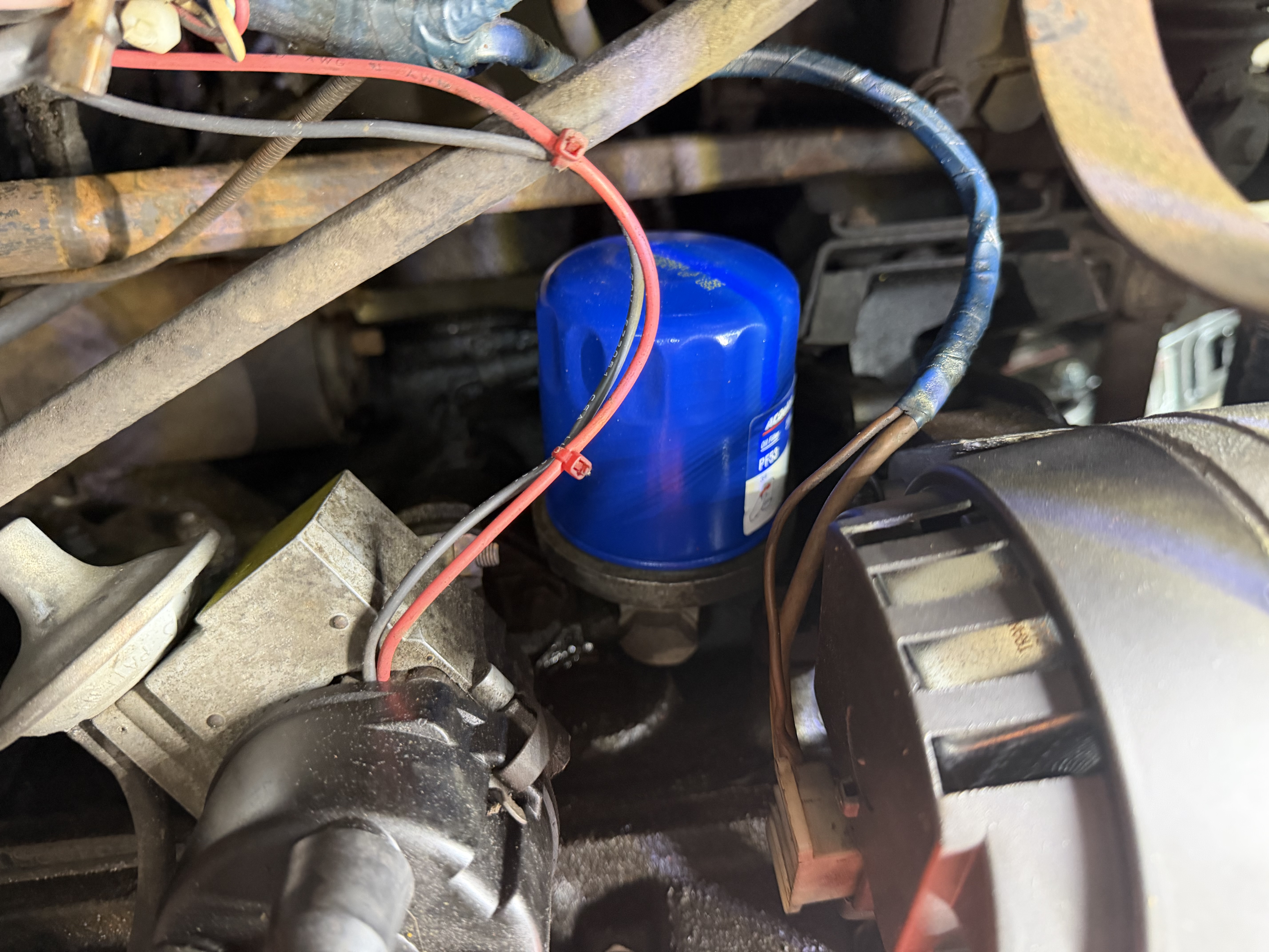
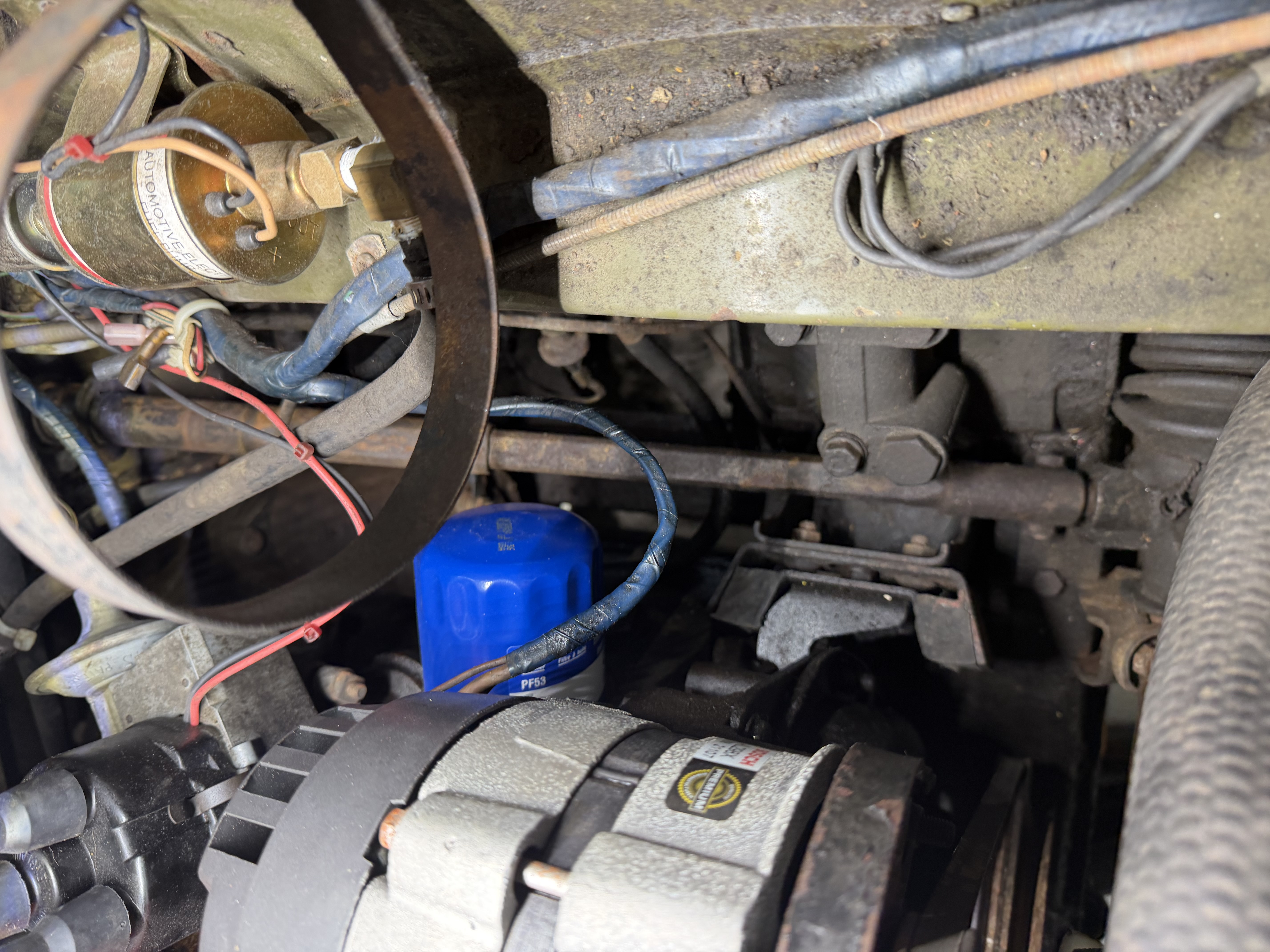
These views are integrated as direct visual evidence. They do not establish hidden thread or seal geometry, calibrated mounting coordinates, electrical compatibility or a verified removal path. Browse all nine new photographs ↗
Separate block oil-pressure relief assembly: four-part bench reference and evidence plan ↗