Support and space
the rocker gear.
Four bored supports, a hollow shaft, eight open followers and separate spacing and retention parts replace four coarse groups in the whole-car model. The existing eight rocker arms, valve positions, shaft axis and engine placement stay.
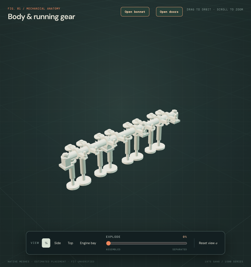
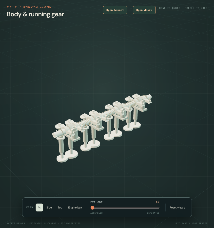
The pushrod span does not reconcile
The 1500 factory plate, PDF p. 62 / printed 107-B88, lists eight 143552 tappets and eight 157508 pushrods. Revington’s own length comparison lists 157508 at 198 mm overall and distinguishes overall length from effective ball-to-cup centers. The model’s eight inherited flat-ended lines span only 130.685 mm. These are different end datums; their numerical difference of 67.315 mm is a reference mismatch, not measured shortfall or a prescription to lengthen a rod.
The separate 198 mm comparison has estimated rounded-end, stem and open cup construction. It sits outside the engine end plane and stays hidden in the normal whole-car view until selected. The eight old pushrod lines, camshaft, head/block passages, rocker axes and engine frame remain in place. No longer part is forced into that unregistered engine layout.
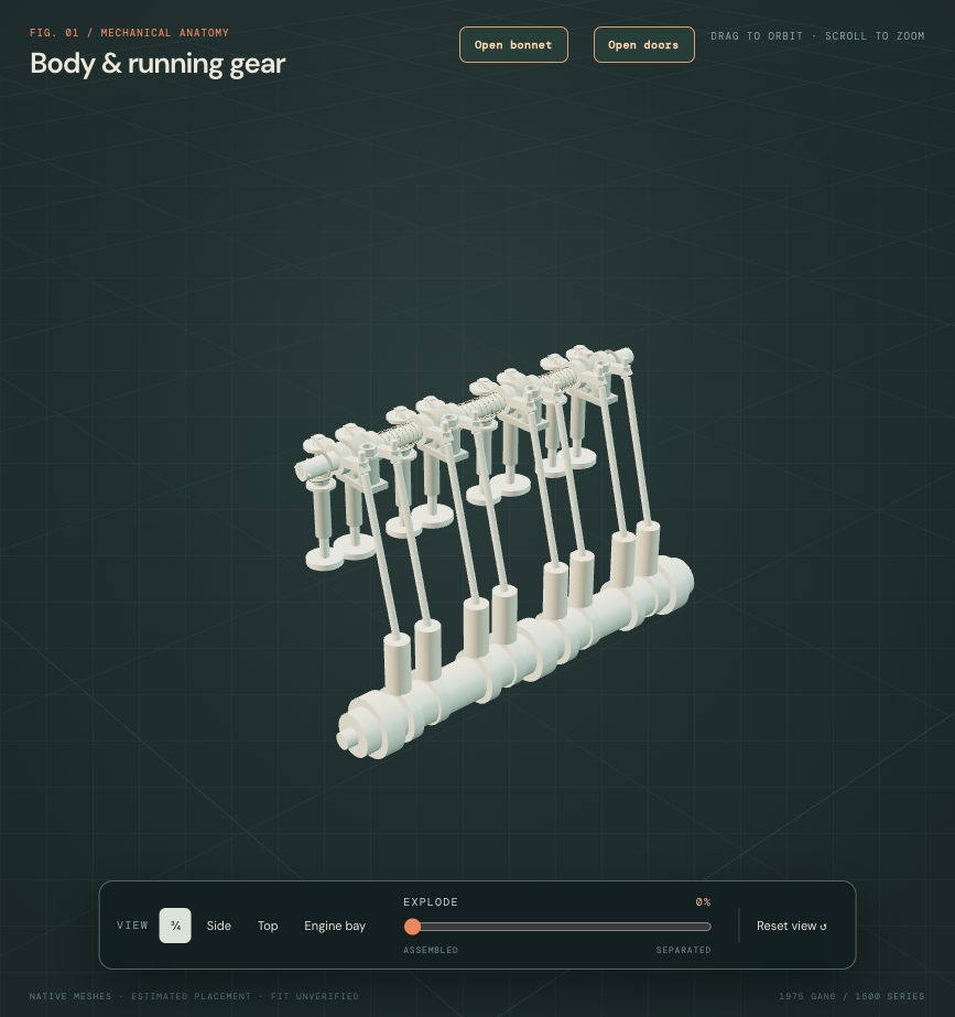
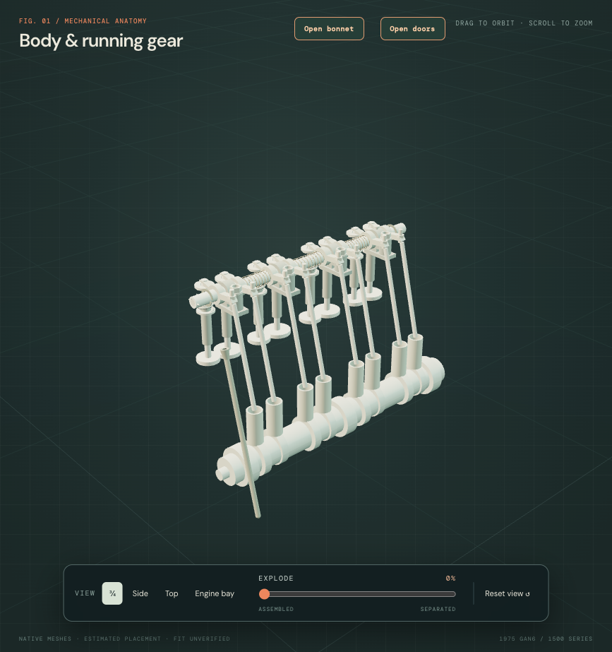
Factory general specification PDF p. 12 / printed 04-2 was visually rechecked: tappet diameter 20.30–20.32 mm and length 44.45 mm. The existing 20.31 × 44.45 mm exterior and axes stay; the supplier photo supports an open barrel. The 16 mm cavity and 5 mm closed floor are estimates. The hidden contact-seat form, floor thickness, oil holes and face crown are unknown. The old rod starts at the rim station, rather than a verified internal seat; this is not a completed cam-to-rocker load path.
The new comparison does not identify a single correction to the cam axis, head height, rocker station or end geometry. The manual’s 62 pitches and 0.375-inch chain pitch were rechecked; that does not validate the model’s photo-inferred sprocket counts or chosen lateral cam offset. The retained camshaft is shown for context; its simple lobes and static follower relationship are recognition geometry, not a working contact or timing solution. No engine geometry is moved simply to make the rod fit, and no valve timing, lash, loaded articulation or removal path is established.
Earlier support and spacing increment
What the factory plate establishes
The 1500 factory parts plate, PDF p. 63 / printed 107-B90, distinguishes 144973 front, two 144974 intermediate and 144975 rear pedestals; 144962 shaft; three 105120 spacing coils; two 105322 end spacing springs; two 146914 plain washers; two 137811 shaft plugs; 104859 locating screw and PC10 cotter. Four HN2009 nuts and WP184 washers retain the supports. These catalog roles do not identify this car’s fitted parts.
Primary supplier photographs of 144975, 105120 and 105322 were inspected. They support a bored shaft support with a separate stud passage, wire spacing coils and split end spring washers. Their unscaled photographs supply no fitted dimensions.
A conditional support layout
The original shaft axis and 344 mm length stay. Its existing 14.24815 mm nominal diameter follows the midpoint converted from the manual’s 0.5607–0.5612 inch range; the inconsistent printed metric pair remains unresolved. The new 8 mm axial bore is an estimate, not a measured oilway.
Support stations now follow the retained valve-pair centers at Z ±122.75 and ±43.25 mm, replacing the arbitrary ±166 and ±55 mm blocks. Stud axes move from X=0 to an estimated X=17 mm offset to express the separate support architecture. All casting dimensions, bores, sections, spring counts of turns, static spacing and washer positions are construction hypotheses. The generic cast shape does not reproduce the different machining of the three factory pedestal types. No head receiver holes are cut, and the inherited rocker handedness and contact geometry remain unverified.
Open passages and nonintersecting reference parts do not establish bearing fit, spring preload, lubrication, shaft locking, stud engagement, valve lash, cover clearance or tool access. Springs and washers are displayed in estimated static positions without a loaded contact solution.
Manual reading and replacement boundaries
Accessible AKM4071/B part 3, PDF p. 7 / printed p. 80, was visually read. Operations 12.29.54 and 12.29.55 are explicitly labelled Engine—U.K. specification. They describe the cover/four pedestal fastenings, front cotter, rear locating screw, preservation of rocker/pedestal/spring/spacer order and clear rocker/shaft oilways. This corroborates component roles; its torque, locking compound and procedure have not been verified as the applicable 1975 North American instructions.
The missing North American engine section remains a documentary gap. The inspection view hides obstacles and uses illustrative translations. It does not prove a safe release state, service sequence, lift direction or actual-car removal path.
Evidence and native files
The historical 233-group engine asset remains unchanged and supplies the fallback if this overlay cannot load. This revision is integrated into the whole-car viewer; the separate detailed-engine viewer retains its historical core.