Connect the main caps
to their fasteners.
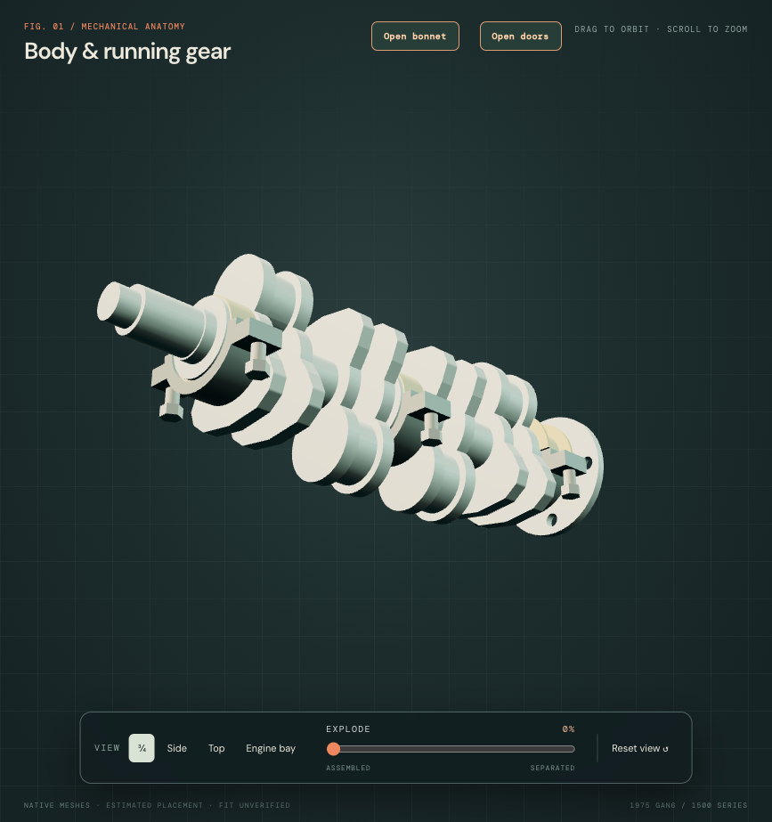
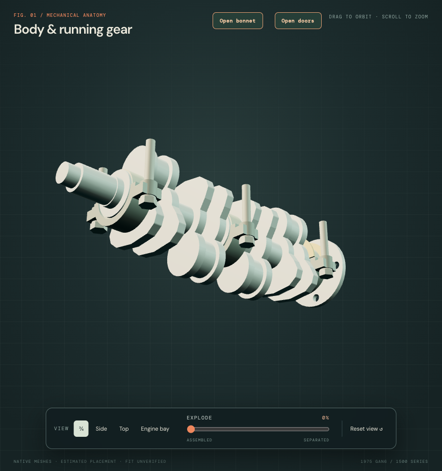
Three separately selectable caps now have open fixing passages, nominal-length smooth bolts and unloaded washer roles. Six bearing halves use the factory reference clearance range around the retained journal size. The block and crank remain unchanged.
Keep nominal specifications separate from fitted measurements
The factory general specifications, PDF p. 11 / printed 04-1, give 58.713–58.725 mm main journals, 21.34–21.72 mm bearing length and 0.013–0.050 mm diametral clearance. Journal and length ranges were already represented. The new shells replace the old 0.20 mm diametral display gap with a selected 0.0315 mm midpoint comparison. Outer shell radius retains the old unmeasured seat allowance. This does not identify your crank size, bearing grade, wear, crush or running oil film.
Factory parts p. 57 / 107-B78 lists six HB1024 bolts and six WL210 washers. The original hardware table, PDF p. 6 / printed 3, gives HB1024 as 7/16 UNF × 3 inches: nominal 11.1125 mm diameter and 76.2 mm under-head length. Conflicting supplier text describing 3½ inches is recorded without applying it. No fitted bolt identity or replacement suitability is asserted.
Make the reference interfaces inspectable
Existing three main stations and six bolt axes stay. Estimated cap pads reach the crank split plane; 12 mm plain passages, selected 18 mm head flats and unloaded split washer envelopes make the cap/head relationship visible. The new shanks are smooth. The 28 mm old shank cues and floating head faces are superseded by nominal-length comparisons seated on declared cap reference faces.
No block hole, blind depth, thread or hidden boss is created. The retained block casting does not establish a fitted receiver at every inherited bolt axis. Shaft-tip material tests and source intersections in the validation file describe that gap; they do not prove engagement, clamping or an actual fastening load path. Cap casting profiles, pads, mounting centers and washer/head details remain estimates.
At the main-cap stage, all 12 source groups contained positive valid geometry: three connected caps, six smooth bolts, six unloaded washers and six shell halves total 21 STEP solids. The connecting-rod extension below retains those groups and adds four rods. Native checks cover cap passages, selected journal/shell sections and declared cap/washer/head faces. They do not establish strength, loaded lubrication, locking, end float, torque, tool access or an actual removal path.
Procedure scope
The accessible UK engine operation on printed p. 77 distinguishes marked caps, shell halves and rear-main thrust washers. It is recorded as UK architecture only. Its tightening sequence and torque are not presented as verified 1975 North American instructions. Both existing thrust washers, crank, block and sump remain held. Inspection separation is illustrative.
Relieve the connecting-rod shanks
The factory Midget drawing, PDF p. 58 / printed 107-B80, lists four 146454 rod assemblies and separate 119813 small-end bushes. A newly reviewed supplier’s own 146454 photograph shows a recessed shank with longitudinal edge flanges and rounded pocket ends. The former solid rectangular stems now become relieved reference shanks on all four rods.
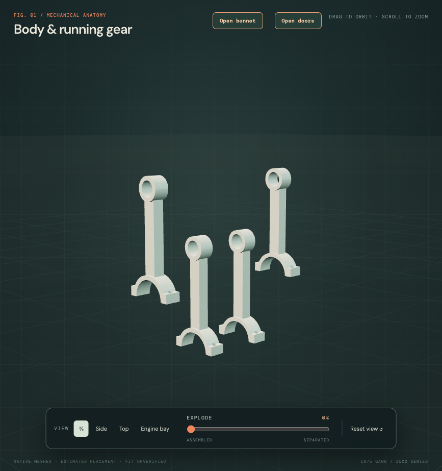
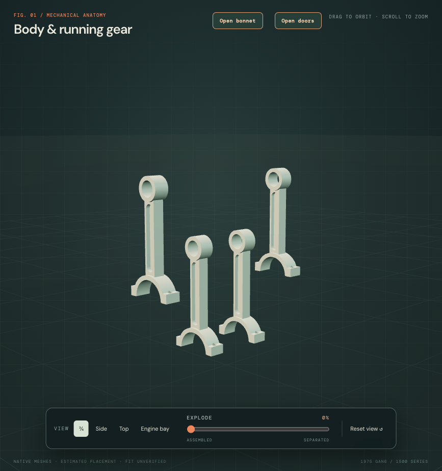
The selected 12.5 mm pocket width, 4 mm central web, pocket length and rounded ends are unmeasured construction choices. Reverse-face relief mirrors the photographed face as an explicit hypothesis; the second supplier image shows packaging and supplies no reverse-face geometry. No lightening/oil hole, casting mark or stamped number is copied.
Both end regions, their bores, axial widths, bosses, cap split and fixing passages stay. The existing center-distance datum stays. End bore/width values came from an earlier aftermarket H-beam comparison; retaining them does not identify a stock 146454 rod or the rods fitted to this car. Caps, fasteners, bearing halves, bushes, crank, pistons and engine pose remain unchanged.
The companion now has 16 groups and 25 positive valid STEP solids. Each new rod is one connected solid; native checks retain material at its web and edge flanges, open both face recesses, and prove the guarded big/small ends and overall bounds unchanged. All 12 previous main-bearing mesh records and native volumes stay. The original engine export remains historical; the whole-car loader replaces the four old rod bodies only after successful import.
This is a static shape comparison, not a forged-part development, material specification, mass balance, strength analysis, working crank/rod sweep or verified replacement/removal procedure. The independent block-side receiver gap above remains unresolved; this revision adds no block material or holes.